6 remote connection – Kohler 13ERG User Manual
Page 29
TP-6335
9/04
Electrical System 19
--
+
Battery
Positive
Vehicle
Frame
12-Volt
Battery
Using the Same Battery
as the Vehicle Engine
N
Battery Negative
to Vehicle Frame
Ground Strap
Vehicle Frame
--
+
Battery
Positive
Vehicle Frame
12-Volt
Battery
Using a Separate Battery
for the Generator Set
N
View A
View B
Figure 6-6
Battery Connection Details
6.6 Remote Connection
Kohler Co. offers several remote panels for connection
to the generator set.
Contact your local Kohler
r
distributor/dealer for detailed descriptions.
See
Figure 6-7 for the location of the remote interface
connection to the generator set junction box. Kohler Co.
also offers wiring harnesses in various lengths with a
connector keyed to the junction box connector.
A
“pigtail” harness is also offered which includes the
appropriate connector on one end and has pigtails that
the installer can use to connect to a customer-supplied
start/stop switch or separate lights and hourmeter.
Consult wiring diagrams, ADVs, and instruction sheets
for connection information/details.
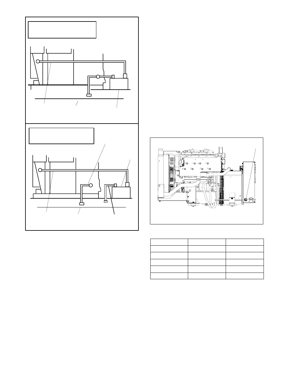
These models use a 12-pin connector for the remote
interface
connection.
See
Figure 6-7
for
the
connector’s location.
See Figure 6-8 for the correct
customer-supplied plug and pin part numbers.
1
GM34867C
1. Remote interface connector
Non-Service Side View
Figure 6-7
Remote Interface Connector
Component
Amp Part No.
Kohler Part No.
Plug
350735-1
229998
Pin
350218-6
241618
Cable Seal
794280-1
GM29252
Interface Seal
794279-1
GM29507
Cavity Plug
770377-1
GM28769
Figure 6-8
Connector Components
Note: Gauge senders. Gauge senders are available
for most generator sets.
If using customer-
supplied gauges, be sure they are compatible
with generator set senders.
Contact an
authorized Kohler
r service distributor/dealer.
Gauges and senders are available as service
items from an authorized Kohler
r service
distributor/dealer.