Troubleshooting/inserting pins, Diagram a, Diagram b – Ikelite pdf #4104.6 ..... Nikonos TTL Cord Film Camera User Manual
Page 3
3
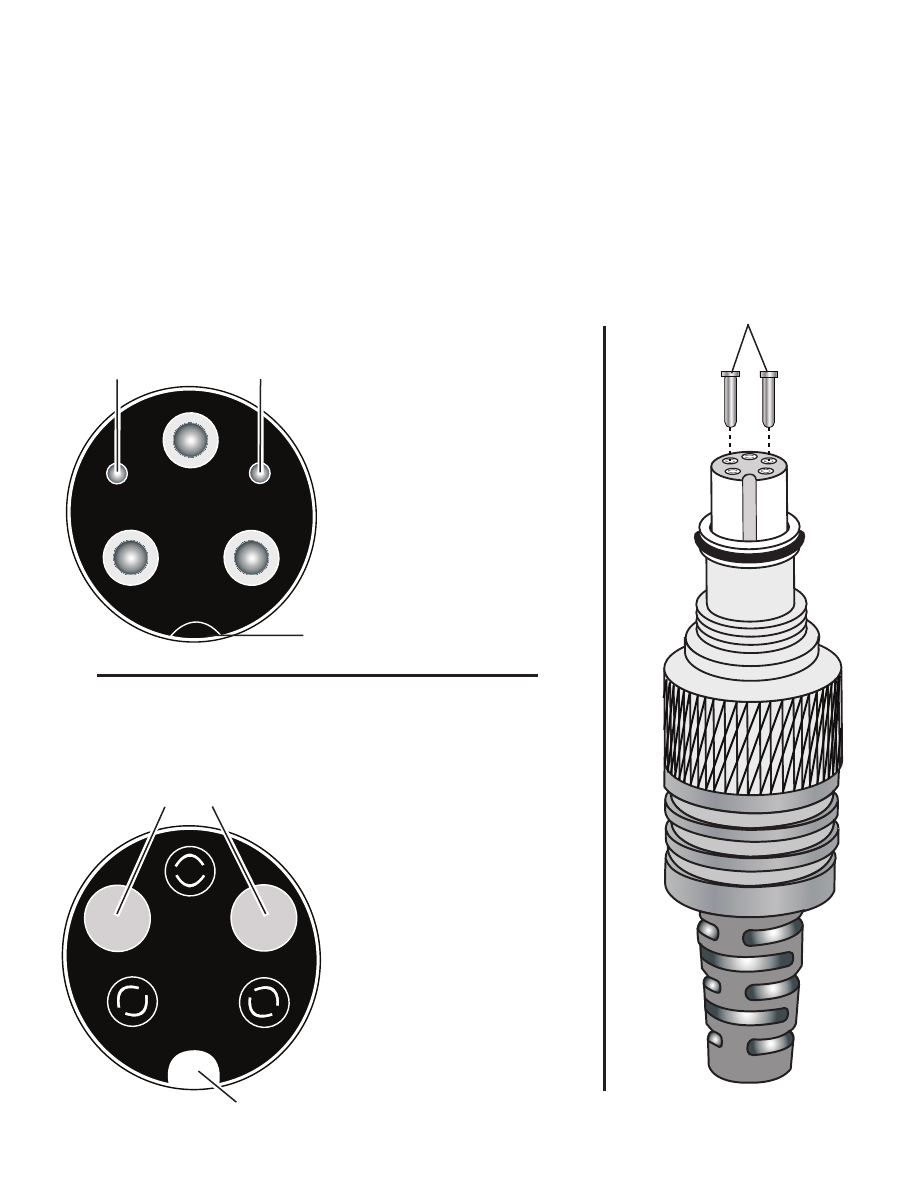
Gold-Plated Pins properly
inserted in Receptacles
Nikonos Connector End
Index Groove
Gold-Plated Pins
Nikonos Housing Bulkhead
Diagram A
Spring-loaded Contacts
Index Post
Diagram B
Troubleshooting/Inserting Pins
- If intermittent or loss of TTL operation occurs, insert the 2
gold plated pins into the Nikonos Connector End corresponding
receptacles as shown, Diagram A. With the Index Groove at the bottom,
the pins should be at the 10 and 2 o’clock positions. Once the pins
are installed they should not be removed.
- Connect the Connector to the camera/housing bulkhead (See page 2
).