30 connector pinout, Table 2.30 connector pinout and pin description, 30 connector pinout -6 – Inova GigaHub PD008310103.001 AB User Manual
Page 19: Table 2.30 connector pinout and pin description -6, Product overview, Gigachampion
©2002 Inova Computers GmbH
Page 2-6
Doc. PD008310103.001
Product Overview
GigaCHAMPION
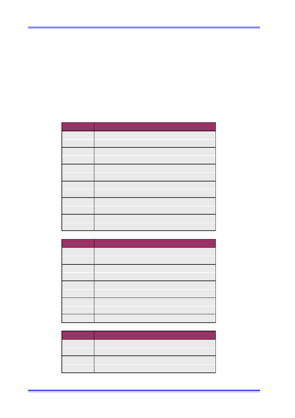
2.30 Connector Pinout
Figure 2.3 shows the physical face-plate connectors on the Inova GigaCHAMPION graphic accel-
erator. Table 2.30 gives the pinout and description of these connectors.
Table 2.30 Connector Pinout and Pin Description
Pin No.
Signal
1
Analog RED
2
Analog GREEN
3
Analog BLUE
4
N/C
5, 6, 7, 8
CRT Ground
9
+5V (DDC Data)
10
CRT Ground
11
N/C
12
DDC-SDA
13
HSYNC
14
VSYNC
15
DDC-SCL
Pin No.
Signal
1
GigaSTAR Tx+
2
Data 1+
3
GND
4
Data 2+
5
N/C
6
GigaSTAR Tx-
7
Data 1-
8
Data 2-
9
GND
Pin No.
Signal
1
+5V
2
USB P0-
3
USB P0+
4
GND
15-pin D-Sub VGA Analog Interface
9-pin D-Sub GigaST
Ȣ
R Interface
4-pin USB-B