Micron Technology Turbofan User Manual
Page 23
DRAFT
22
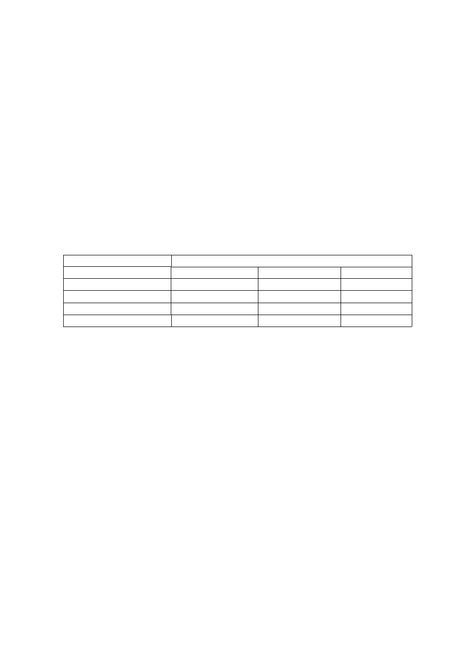
RESTRICTOR No.
FLOW RATE (litres/minute)
1 Bar (15 psi)
2 Bar (30 psi)
3 Bar (45 psi)
10
0.30
0.42
0.51
48
0.62
0.87
1.07
55
0.81
1.14
1.40
86
2.05
2.90
3.55
7. Fit the appropriate orifice in the fixed restrictor of each sprayhead.
8. Place a container under each sprayhead.
9. Ensure that the chemical on/off valve is closed.
10. Fill the tank of the sprayer with at least 50 litres of the chemical to be used or a liquid
of similar properties.
11. Start the chemical pump of the sprayer but do not run the hydraulic system.
12. Open the chemical valve until all air is purged from the hoses and sprayheads.
Return the chemical collected in the containers to the tank of the sprayer.
13. Place the containers back under the sprayheads and open the chemical on/off valve
again and collect chemical for a measured time of one or two minutes. Use a
measuring cylinder or calibrated container to measure the output and calculate the
flow rate in litres per minute per sprayhead.
14. Check that the flow from each sprayhead is the same and compare the total measured
output rate from all the sprayheads with the calculated rate from step (4).
15. If the actual output is slightly too high or too low, it may be possible to adjust it by
varying the spray chemical pressure.
16. If this adjustment is insufficient, the restrictor orifice for each sprayhead must be
changed to a smaller size to reduce the flow or a larger size to increase the flow.
17. The flow must always be re-checked after making any adjustments to the restrictors
or chemical pressure.
Table 3. Approximate flow rates for fixed restrictor orifices
5. Calculate the output of each sprayhead by dividing the total output of the sprayer by
the number of sprayheads.
Example:
Output:
16 l/min from sprayer
No of sprayheads:
8
Output/sprayhead
=
16/8
=
2 l/min
6. Select the correct fixed restrictor orifice to give the required flow rate per sprayhead
at the normal working pressure of the sprayer (typically about 2 bar or 30 psi). Table
3 gives the typical flow rates for fixed restrictor orifices. These figures are based on
measurements with water. Actual flow rates may differ according to the viscosity of
the chemical being used.