Appenb.pdf, B.1 crt (vga) connector, Pin assignments – FIC A360 User Manual
Page 175: Appendix
Pin Assignments
FIC A550 Service Manual
B-1
Appendix
B
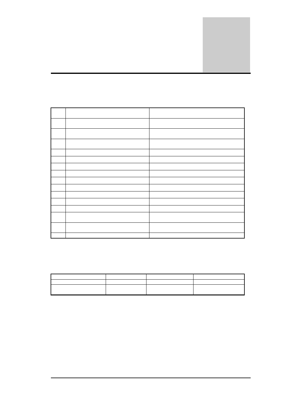
B.1 CRT (VGA) Connector
The pin assignment of the VGA connector is as follows:
No PIN
ASSIGEMENT(by:
sort)
DESCRIPTION
1
RED Video_5 :O (analog)
Red this DAC analog output drives the CRT
interface.
2
GREEN Video_5 :O
(analog)
Green this DAC analog output drives the CRT
interface.
3
BLUE Video_5 :O
(analog)
Blue this DAC analog output drives the CRT
interface.
4
Monitor ID Bit 2 :
Option
5 GROUND
:
Ground
6
RED Return (ground) :
Ground
7
GREEN Return (ground) :
Ground
8
BLUE Return (ground) :
Ground
9
KEY (no connector) :
VCC
10
SYNC Return (ground) :
Ground
11
MONITOR ID Bit 0_5 :
Monitor Sense Indicator
12
MONITOR ID Bit 1_5 :I
DDC monitor data
13
HORIZONTAL SYNC_5 :O (t/s)
CRT Horizontal Sync this output is The
Horizontal sync pulse for the CRT Monitor.
14
VERTICAL SYNC_5 :O (t/s)
CRT Vertical Sync this output is the Vertical
sync pulse for the CRT Monitor.
15
MONITOR ID Bit 3_5 :I/O
DDC monitor clock
Absolute Maximum Conditions
The following parameters are maximum ratings for VGA. Permanent device damage may
occur if these rating are exceeded. Extended exposure to these ratings may also cause device
failure.
PARAMETER MIN
MAX
UNIT
I/O VOLTAGE
-0.5
+6.00V
V
OUTPUT CURRENT
-12mA(source)
+24mA(sink)
m A