Single and multi-stage conventional heat operation, Com led operation, Purge mode – Honeywell ENVIRAZONE PANEL W8835 User Manual
Page 9: Individual zone fan control
W8835 ENVIRAZONE PANEL
9
68-0258—04
COM LED Operation
The green COM LED flickers as the W8835 communicates
with the other EnviraCom devices:
LED blinks rapidly—indicates device is currently
transmitting information on the communications bus.
LED blinks once—indicates device received and
acknowledged a message.
LED on constantly— indicates panel failure. Replace panel.
LED off constantly—indicates a wiring problem.
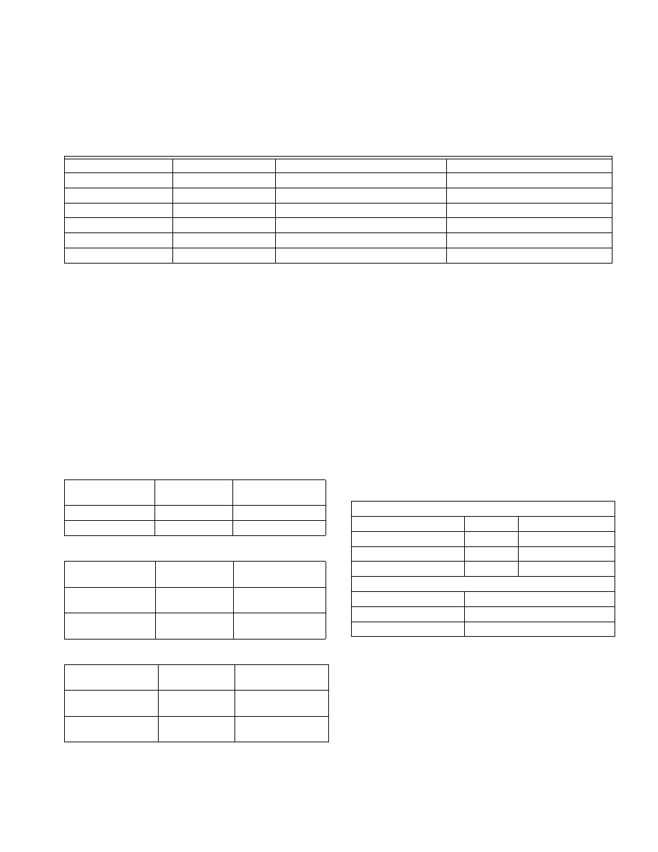
Table 3. LED Indicators
b
b
An LED change precedes the corresponding relay change by as much as six seconds.
Purge Mode
At the end of every call for heat or cool, the panel enters a
Purge mode. DIP 4 configures the panel to purge for two
(default) or three and one-half minutes. DIP switch 5
configures the panel or the HVAC equipment to operate the fan
during purge.
The Purge LED lights to signal that the system is in the Purge
mode. Pressing the purge override button overrides the Purge
mode.
Unless there is a new call for heat or cool during the Purge
mode, all dampers are moved to the Open position at the end
of purge. DIP switch 6 is used if it desired to open all dampers
during the Purge mode.
Table 4. Purge Configuration
Table 5. Fan Control Configuration
Table 6. Purge Damper Configuration
Individual Zone Fan Control
When all zones are satisfied, the fan switch of each thermostat
controls the fan operation for that zone. When the fan setting is
“ On”, the fan is energized, the fan LED illuminates and the
dampers close to zones where the fan setting is “Auto”. If there
is a call for heat or cool during this time, the fan mode ceases,
and the heat or cool call is honored. When the zone calling is
satisfied, and Purge mode has ended, the fan call resumes.
Single and Multi-Stage Conventional
Heat Operation
The panel can control up to three stages of heating and two
stages of cooling based on thermostat demand. Set DIP
switches 1 and 2 for 1, 2 or 3 stages of heat. Set DIP switch 7
for one or two stages of cooling.
Table 7. Conventional Equipment Configuration
LED
Color
Illuminated
Not Illuminated
Heat
Red
Heat call.
No heat calls.
Cool
Green
Cool call.
No cool calls.
Purge
Amber
Purge mode.
Not in Purge mode.
Fan
Green
Fan only call.
No fan only call.
Em Heat
Red
Emergency Heat mode.
Not in Emergency Heat mode.
Zone 1, 2, 3
Green
Damper is open or opening.
Damper is closed or closing.
DIP Switch
Number
Status
Purge
4
Off (Down)
3.5 minutes purge
4
On (Up)
2 minutes purge
DIP Switch
Number
Status
Fan Control
5
Off (Down)
Panel control of fan
in Purge
5
On (Up)
HVAC control of fan
in Purge
DIP Switch
Number
Status
Purge Damper
6
On (Up)
Last zone(s) calling
open during Purge
6
Off (Down)
Open all dampers
during Purge
1 Stage Cooling
Equipment Type
DIP 1
DIP 2
1 Stage Conventional
On (Up)
On (Up)
2 Stage Conventional
On (Up)
Off (Down)
3 Stage Conventional
Off (Down)
On (Up)
2 Stage Cooling
Cooling Stage
DIP7
1 Stage
On (Up)
2 Stage
Off (Down)