Caution, 3oxpelqj6dggoh9doyh, He360a,b powered flow-through humidifier – Honeywell HE360A User Manual
Page 5
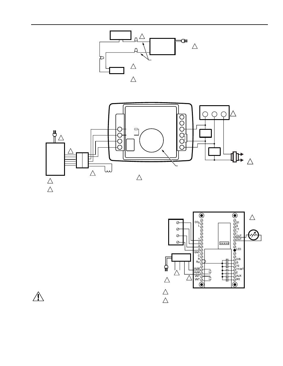
HE360A,B POWERED FLOW-THROUGH HUMIDIFIER
5
68-0194—2
SAIL
SWITCH
HUMIDIFIER
120 VAC
M12685
YELLOW WIRES
1
1
2
2
POWER SUPPLY. PROVIDE DISCONNECT
MEANS AND OVERLOAD PROTECTION
AS REQUIRED.
24V WIRING.
MECHANICAL
HUMIDISTAT
Fig. 8. Typical wiring diagram of sail switch with humidifier.
DEHUM
YELLOW
YELLOW
RED
RED
BLACK
BLACK
DEHUM
HUM
HUM
K1
HOT
COM
OUT
OUT
G
CG
CW
W
24VAC
HUMIDIFIER
CONNECTOR
SOLENOID
FROST FACTOR
SETPOINT DIAL
1
1
2
3
POWER SUPPLY. PROVIDE DISCONNECT MEANS
AND OVERLOAD PROTECTION AS REQUIRED.
24V WIRING.
120
VAC
1
2
ELECTRONIC HUMIDISTAT
M12820A
HEAT ONLY APPLICATIOIN SHOWN. SIMILAR WIRING
REQUIRED IN HEAT AND COOL SYSTEM WITH ONE
OR TWO TRANSFORMERS.
ROOM THERMOSTAT
3
L1
(HOT)
L2
1
R
W
G
FAN
RELAY
HEAT
RELAY
FURNACE
TRANSFORMER
Fig. 9. Typical wiring diagram for humidifier using H1008 Automatic Humidity Control.
)RU3HUIHFW&OLPDWH&RPIRUW&HQWHU
&RQWURO
&RQQHFWLRQV
1. Connect only the two yellow wires to the W8900 (red
wire connections are not used). See the typical
wiring diagram in Fig. 10.
For additional mounting and wiring information, refer to the
Perfect Climate Comfort Center
installation instructions.
3OXPELQJ6DGGOH9DOYH
Hot or cold water, either hard or softened, can be used in
the humidifier.
1. Use the self-piercing saddle valve included to tap
into the water supply line at an appropriate location.
CAUTION
Equipment Hazard.
Improper installation can cause equipment
damage.
Do not use any line connected to an air
conditioner.
W8900B
PC8900
1
2
3
4
M12819
HE360
HUMIDIFIER
OPTIONAL
OUTDOOR
AIR SENSOR
1
2
2
2
3
POWER SUPPLY. PROVIDE DISCONNECT MEANS AND OVERLOAD
PROTECTION AS REQUIRED.
OPTIMAL CONTROL ACHIEVED WHEN USING OUTDOOR AIR SENSOR.
YELLOW
YELLOW
RED
RED
120
VAC
1
Fig. 10. Typical wiring diagram for humidifier using
PC8900/W8900.