Warning – Honeywell HE360A User Manual
Page 4
HE360A,B POWERED FLOW-THROUGH HUMIDIFIER
68-0194—2
4
M12813
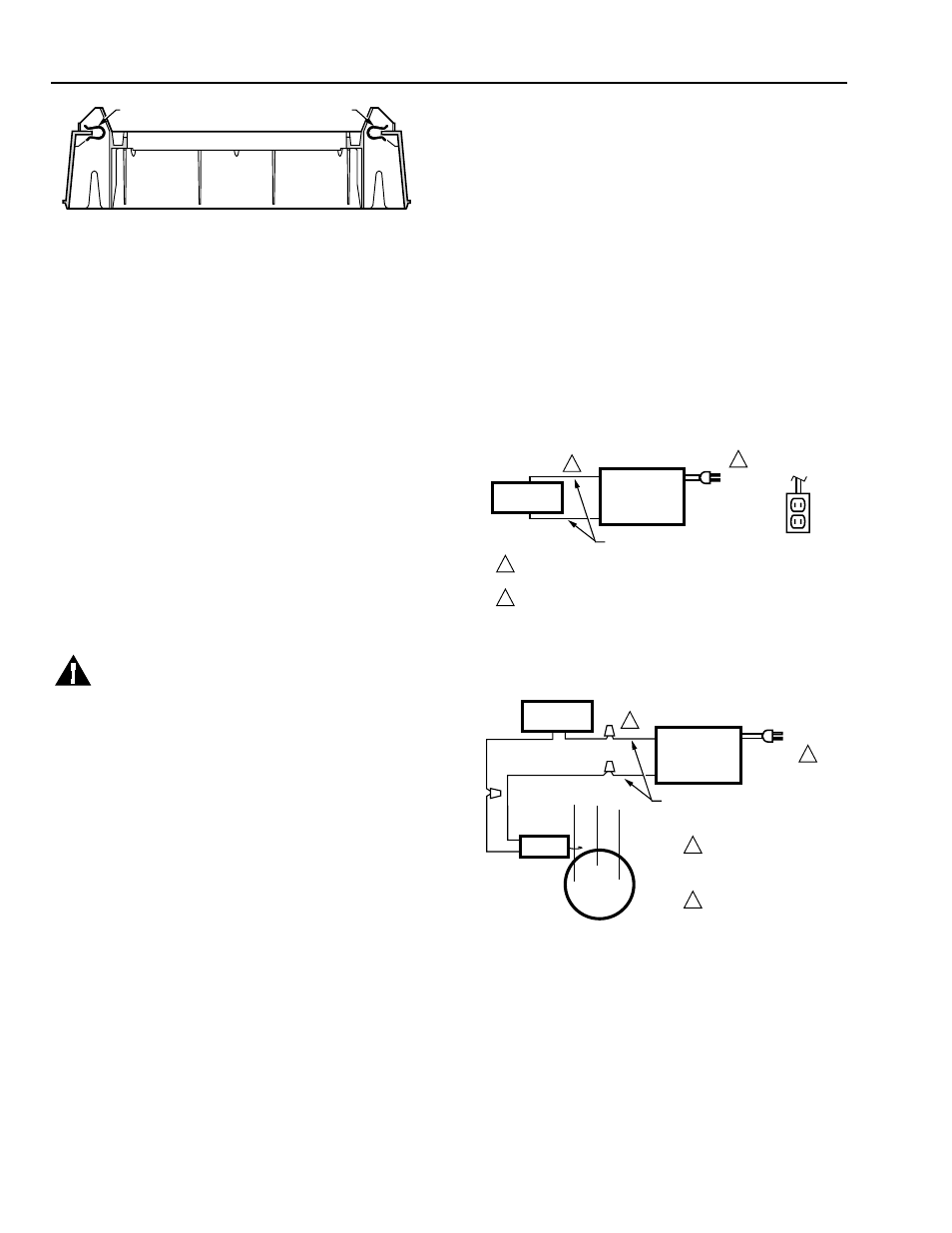
CLIP
CLIP
Fig. 5. Position securing clips.
7. Position the humidifier housing in the hole (be sure it
is level), so the locking tabs are in place on the
upper and lower sheet metal edges of the hole.
8. Push in the securing clips until completely seated.
9. Drill holes and install the three sheet metal screws at
the top of the humidifier housing. Secure the housing
with the three remaining screws at the bottom of the
housing.
10. Reinstall the humidifier pad assembly in the
humidifier housing.
IMPORTANT
For proper operation, be sure the mark on the
end of the humidifier pad is facing up. Check that
the water feed tube is placed in the guide slots of
the humidifier housing.
11. Hook the top of the cover to the housing and secure
with the thumbscrew located at the bottom of the
cover.
:,5,1*+80,',),(5
WARNING
Serious Personal Injury or Equipment Hazard.
Moving parts can cause electrical shock and
injury.
•
Disconnect power supply before installation or
servicing.
•
This device contains a moving fan blade; do not
operate the humidifier without the cover
securely attached.
All wiring must comply with applicable local codes,
ordinances and regulations.
)RU++XPLGLVWDW+&RQYHUWLEOH+XPLGLW\
&RQWURO:LULQJ&RQQHFWLRQV
IMPORTANT
•
Select models of fan centers include humidifer
taps so the current sensing relay or sail switch is
not needed.
•
If not using a current sensing relay or sail switch,
the 120V humidifier plug must be energized
during blower motor cycles for proper operation.
1. Wire the current sensing relay or sail switch.
2. Connect only the two yellow wires to the humidity
control (red wire connections are not used for
mechanical humidity control). See the typical wiring
diagrams in Fig. 6 through 8.
For additional mounting and wiring information, refer to the
humidity control installation instructions.
)RU+$XWRPDWLF+XPLGLW\&RQWURO:LULQJ
&RQQHFWLRQV
IMPORTANT
Current sensing relay or sail switch is not needed
with the Automatic Humidity Control.
1. Connect the two red and two yellow wires to the
electronic humidity control as shown in Fig. 9.
For additional mounting and wiring information, refer to the
humidity control installation instructions.
HUMIDIFIER
MECHANICAL
HUMIDISTAT
120 VAC
TO BLOWER
MOTOR
IGNITION BOX
M12686
YELLOW WIRES
1
1
2
2
POWER SUPPLY. PROVIDE DISCONNECT MEANS AND
OVERLOAD PROTECTION AS REQUIRED.
24V WIRING.
Fig. 6. Typical wiring diagram for humidifier using fan
control to cycle blower motor fan and humidifier
simultaneously.
CURRENT
SENSING
RELAY
HUMIDIFIER
120 VAC
BLOWER
MOTOR
C
LO
HI
M12684
YELLOW WIRES
1
1
2
2
POWER SUPPLY.
PROVIDE DISCONNECT
MEANS AND OVERLOAD
PROTECTION AS REQUIRED.
24V WIRING.
MECHANICAL
HUMIDISTAT
Fig. 7. Typical wiring diagram of current sensing relay
with humidifier.