Replacement parts – Heatcraft Refrigeration Products H-IM-77D User Manual
Page 5
5
Motor Heater
Model
No. of Amps. Amps.
Size
Motors
A*
B*
A*
B*
09
1
0.8
0.4
4.1
2.07
12
2
1.6
0.8
5.22
2.61
16
2
1.6
0.8
6.09
.04
21
1
1.0
0.5
9.57
4.78
28
-
1.2
-
5.7
5
2
-
1.0
-
7.0
5
-
1.5
-
8.5
Part
115 Volt
208-230 Volt
Description
09
12
16
21
09
12
16
21
28
35
53
Motor
2500701 2500701
2500701
250201
2500801
2500801
2500801
25001
2500801
25001
25001
Fan Blade
5101B
5101B
5101B
2100201
5101B
5101B
5101B
2100201
5101B
2100201
2100201
Fan Guard
5054D
5054D
5054D
H5028
5054D
5054D
5054D
H5028
5054D
H5028
H5028
Heater
459N
4540N
4541N
4545N
4542N
454N
4544N
4546N
H50097
24700701
24700702
Heater Clip
554J
554J
554J
554J
554J
554J
554J
554J
H5009
554J
554J
Defrost Control
5709L
5709L
5709L
5709L
5709L
5709L
5709L
5709L
5709L
5709L
5709L
Mount
91179001
91179001
91179001
2101401
91179001
91179001
91179001
2101401
91179001
2101401
2101401
Step “A” - Normal Refrigeration Cycle
1.. Power.is.supplied.to.N.and.4.terminals.by.the.timer.
2.. The.fan.delay.and.defrost.termination.thermostat.is.closed.in.the..
.
fan.delay.position.and.open.in.the.defrost.termination.position.
3.. The.defrost.heater.is.off.
4.. The.compressor.operates.in.accordance.with.the.demands.of.the..
.
refrigeration.system.temperature.and/or.pressure.controls.
5.. The.unit.cooler.fan.operates.continually.
6.. Frost.builds.up.slowly.on.the.evaporator.
Step “B” - Defrost Cycle
1.. Defrosting.of.the.evaporator.is.started.automatically.by.the.timer..
.
at.predetermined.times.-.typical.settings.of.the.timer.would.be.1.to..
.
3.defrost.periods.per.24.hours.
2.. The.timer.mechanically.opens.switch.“A”.which.breaks.the.circuit.to..
.
the.compressor.and.evaporator.fan.motors,.thereby.shutting.them..
.
off,.and.closes.switch.“B,”.thereby.permitting.current.to.flow.to..
.
the.heater.
3.. The.heater.recessed.in.slots,.gives.up.heat.directly.to.the.fins.of.the..
.
evaporator...This.heat.raises.coil.and.refrigerant.temperature...
.
to.32
º
F.causing.the.frost.to.melt.
4.. Frost.on.the.evaporator.is.melted.and.defrost.water.drips.into.the..
.
heated.drain.pan.and.flows.down.the.drain.
5.. When.frost.has.completely.melted.from.the.coil,.the.coil.starts.to..
.
warm.up.beyond.32
º
F.
Step “C” - Coil Re-Cooling Cycle
1.. When.the.coil.warms.up.to.55
º
F,.the.defrost.termination.thermostat..
.
closes.which.allows.the.current.to.flow.to.the.solenoid.in.the.timer,..
.
which.then.energizes.and.trips.the.timer.switch.back.to.its.normal..
.
position.(switch.“A”.closed,.switch.“B”.open)..The.fan.delay.portion..
.
of.this.thermostat.is.now.open.
2.. The.compressor.now.starts.
3.. Then.fan.motors.remain.off.because.the.fan.delay.thermostat.is..
.
open..This.prevents.warm.air.from.being.blown.into.the..
.
.
refrigerated.space.
4.. The.evaporator.coil.cools.down.approaching.operating..
.
.
temperature..Superheated.gas.only.passes.to.the.compressor.
Step “D” - Return to Normal
Refrigeration Operation
1.. When.the.coil.temperature.reaches.35
º
F,.the.fan.control.switch..
.
closes...This.allows.current.to.flow.to.the.fan.motor.and.the.unit.is..
.
now.back.in.operation.as.in.Step.“A.”
IMPORTANT
1.. On.initial.“pull.down”.of.a.warm.box,.the.fan.will.not.start.until.coil..
.
temperature.reaches.approximately.35
º
F..If.box.is.still..
.
.
comparatively.warm.(60
º
F).when.the.fan.starts,.then.blowing.this..
.
warm.air.over.the.coil.may.cause.it.to.warm.up.to.55
º
F.and.thus..
.
stop.the.fan..Therefore,.fan.may.recycle.several.times.on.initial..
.
“pull.down.”
2.. The.timer.has.an.adjustable.fail-safe.feature.which.will.return.the..
.
system.to.the.refrigeration.cycle.at.the.end.of.a.predetermined..
.
time.(factory.set.at.24.minutes).if.automatic.control.devices.fail.
3.. Frequent.defrost.periods.are.not.necessary!.The.determining.factor..
.
for.number.of.defrosts.per.day.is.the.frost.load..When.frost.“build-.
.
up”.results.in.a.loss.of.refrigeration.capacity,.then.a.defrost.is...
.
required...One.to.three.defrosts.per.day.are.recommended.
4.. A.low.temperature.thermostatic.expansion.valve.with.pressure..
.
limiting.feature.is.desirable.for.use.with.these.units..Such.a.valve..
.
prevents.feeding.of.refrigerant.to.the.coil.during.the.defrost.cycle.
Sequence of Operation
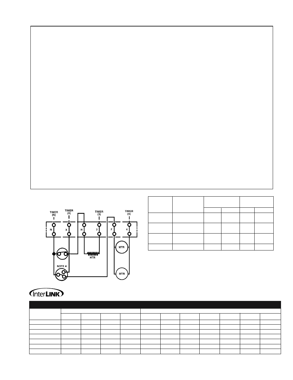
Typical Wiring Diagram for Thin Profile
Electric Defrost Unit Cooler
1.. Use.copper.conductors.only.
2.. Unit.must.be.grounded.
3.. Timer-Paragon.Model.8145-20.may.be.factory.supplied,
.
field.installed,.or.field.supplied.and.installed.
4.. Fan.delay.and.defrost.termination.-.Red.to.N,.Brown.to.X,
.
Black.to.F...Fans.will.not.operate.until.thermostat.resets.
5.. Heater.limit:..Red.to.N,.White.to.H.omitted.on.model.28;
.
heater.is.connected.directly.to.N.
6.. *Indicates.electrical.code:.A=115/60/1,.B=208-230/60/1.
Commercial Refrigeration Parts
Replacement Parts