Assembly – HTC 110163 / CZ38 User Manual
Page 8
8
ASSEMBLY
5
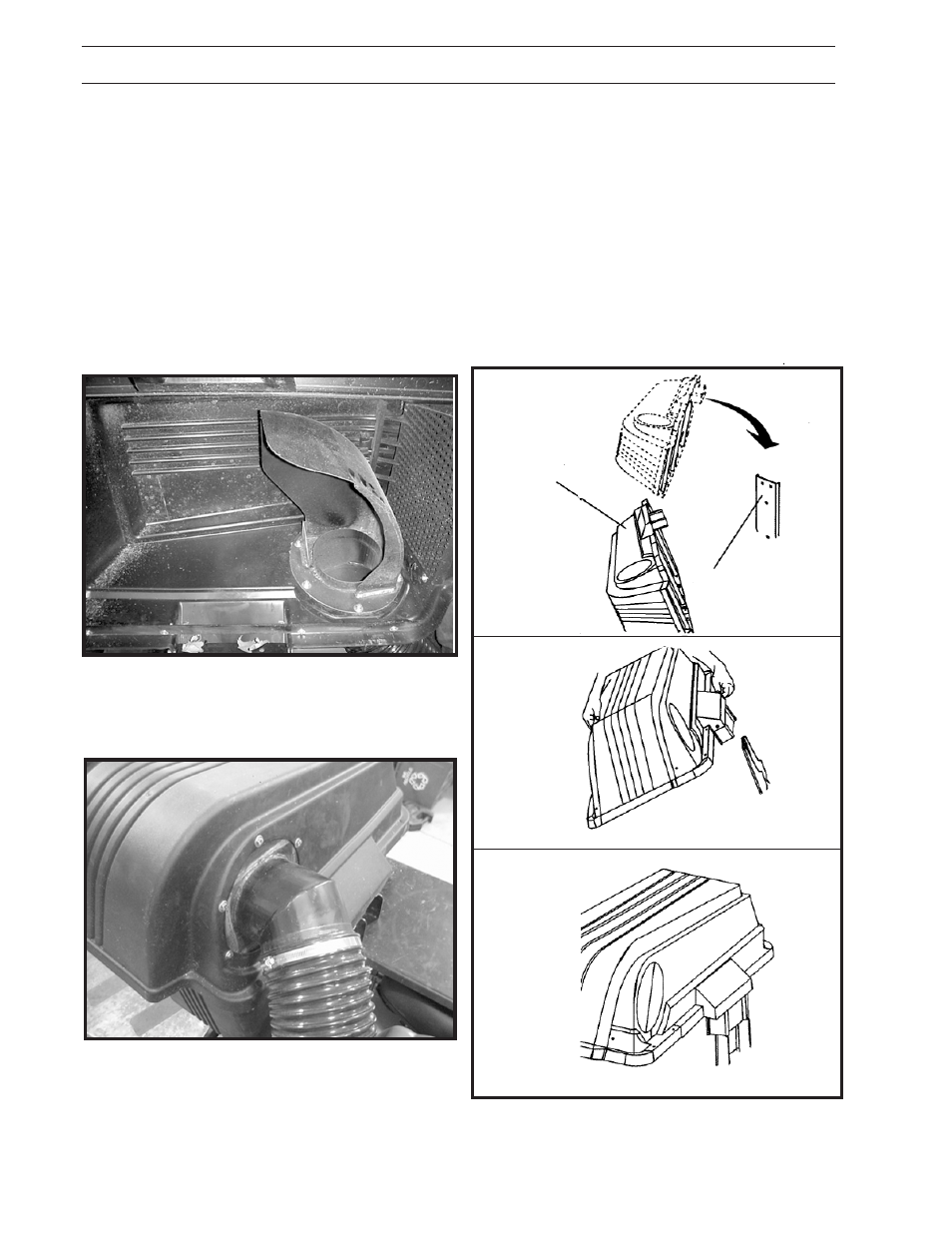
MOUNTING COVER ASSEMBLY TO
SUPPORT ASSEMBLY
(See Figure 5)
NOTE: For ease of assembly, you may wish to
obtain the assistance of another person for
mounting cover assembly to mower.
1. Position cover assembly on ground behind
mower as shown.
2. Lift and rotate cover to align cover brackets
with support assembly.
3. Slide cover assembly down onto the support
assembly.
FIGURE 5
COVER
ASSEMBLY
SUPPORT
ASSEMBLY
4
INSTALLATION OF THE INLET
(See Figure 4A and 4B)
1. Place the cover assembly upside down on a
table. Secure the six bolts (HCS 1/4 x 3/4),
nyloc nuts (1/4) and twelve flat washers (1/4).
2. Place one washer on each bolt.
3. Place the inlet in the cover and direct it out of
the large hole on the front side of the cover.
4. Place the bolt and washer thru each of the six
holes. See Figure 4.
5. Place the other six washer and nuts on the
bolts and tighten.
FIGURE 4A
INSIDE COVER
FIGURE 4B
OUTSIDE COVER