B. vent components diagrams (continued) – Heat & Glo Fireplace Heat & Glo 6000GL-IPI-R User Manual
Page 66
Heat & Glo • 6000GL-IPI-R, 6000GL-IPI-S • 2102-900 Rev. R • 6/09
66
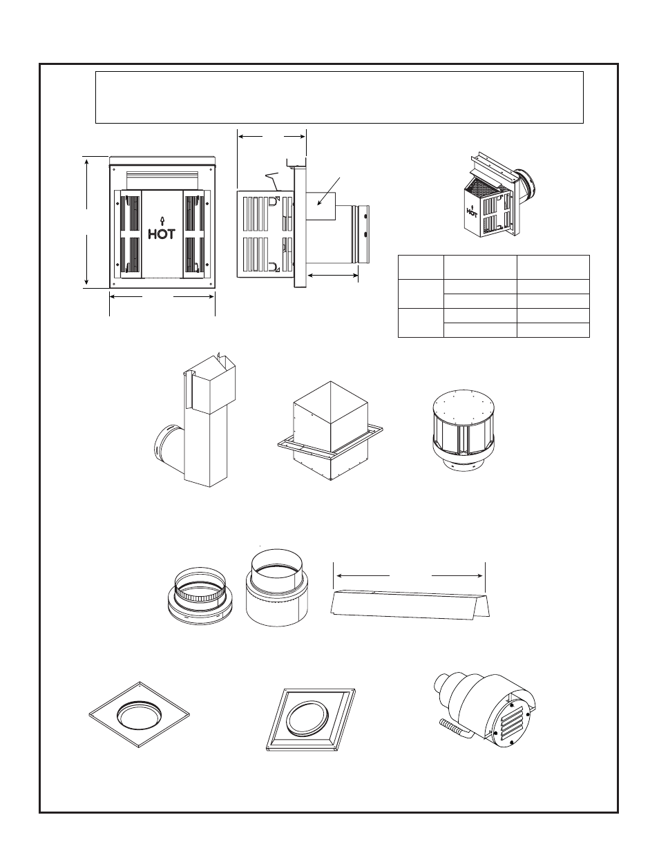
B. Vent Components Diagrams (continued)
Figure 16.8 SLP Series Vent Components
SLP-SNKD
Snorkel
Termination Cap
SLP-TVHW
Vertical
Termination Cap
SLP-CCS-BK
Cathedral Ceiling
Support Box-Black
SLP-DCF-BK
Ceiling Firestop
Black
SLP-WT-BK
Wall Thimble-Black
DVP-2SL
26 in.
660 mm
DVP-HSM-B
Extended Heat Shield
SLP-TRAP
Horizontal Termination Cap
15-1/8 in.
(384 mm)
Note: Heat shields MUST overlap by a minimum of 1-1/2 in. (38 mm). The heat shield is designed to be
used on a wall 4 in. to 7-1/4 in. (102 mm to 184 mm) thick. If wall thickness is less than 4 in. (102 mm)
the existing heat shields must be field trimmed. If wall thickness is greater than 7-1/4 in. (184 mm) a
DVP-HSM-B will be required.
Heat
Shield
Term Cap
Minimum
Effective Length
Maximum
Effective Length
Trap1
3-1/8 in.
4-3/4 in.
79 mm
121 mm
Trap2
5-1/4 in.
9-1/4 in.
133 mm
235 mm
8 in.
(203 mm)
12 in.
(305 mm)
Max
Effective
Length
PVK-80
(For use with IPI and DSI appliances only.)