Vent clearances and framing, A. pipe clearances to combustibles, B. wall penetration framing – Heat & Glo Fireplace Heat & Glo 6000GL-IPI-R User Manual
Page 33
Heat & Glo • 6000GL-IPI-R, 6000GL-IPI-S • 2102-900 Rev. R • 6/09
33
A. Pipe Clearances to Combustibles
WARNING! Risk of Fire! Maintain air space clearance to
vent. DO NOT pack insulation or other combustibles:
• Between ceiling fi restops
• Between wall shield fi restops
• Around vent system
Failure to keep insulation or other material away from
vent pipe may cause over heating and fi re.
8
8
Vent Clearances and Framing
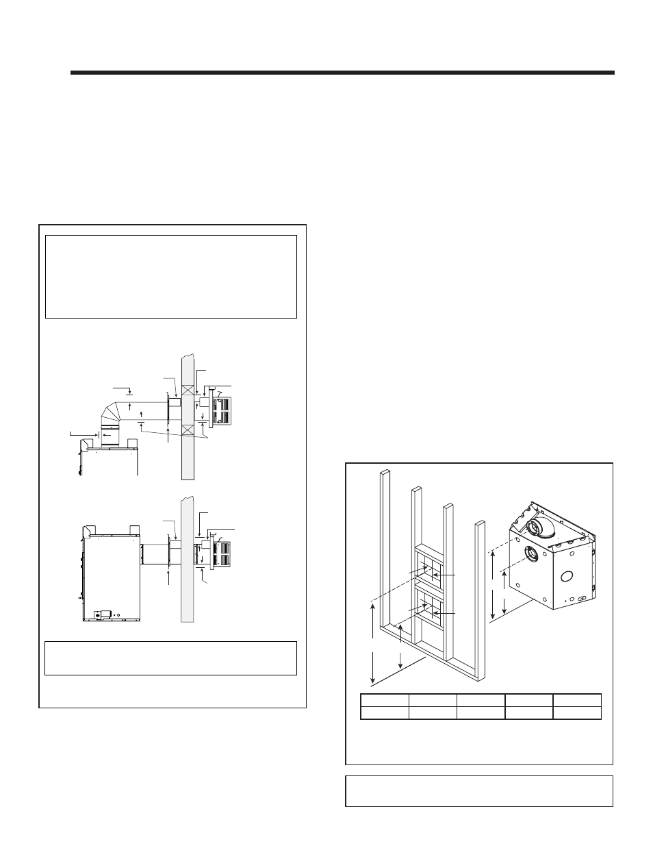
Figure 8.1 Horizontal Venting Clearances To Combustible
Materials
* When using SLP or SL-D pipe, minimum clearances from the vent pipe to combus-
tible materials at inside wall firestops are: Top: 2-1/2 in. (64 mm)
Bottom: 1/2 in. (13 mm)
Sides: 1 in. (25 mm)
Note: Heat shields MUST overlap by a minimum of 1-1/2 in. (38 mm).
• DVP heat shield - designed to be used on a wall 4 in. to 7-1/4 in. (102 mm to 184
mm) thick.
• If wall thickness is less than 4 in. the existing heat shields must be field trimmed. If
wall thickness is greater than 7-1/4 in. a DVP-HSM-B will be required.
• SLP heat shield - designed to be used on a wall 4-3/8 in. to 7-5/8 in. (111 mm to
194 mm thick).
• If wall thickness is less than 4-3/8 the existing heat shields must be field trimmed.
If wall thickness is greater than 7-5/8 in. a DVP-HSM-B will be required.
(DVP-SLP Pipe Shown)
3 in. (76 mm)
top clearance *
1 in. (25 mm)
clearance
bottom & sides
Heat
Shield
Wall
Shield
Firestop
Heat
Shield
WALL
3 in. (76 mm)
top clearance *
1 in. (25 mm)
clearance
bottom & sides
Heat
Shield
Wall
Shield
Firestop
Heat
Shield
WALL
3 in. (76 mm)
top clearance
1 in. (25 mm)
clearance around
vertical sections
A*
B*
10 in.
12 in.
C
D
10 in.
12 in.
Figure 8.2 Wall Penetration
* Shows center of vent framing hole for top or rear venting. The center of the
hole is one (1) in. (25.4 mm) above the center of the horizontal vent pipe.
A*
B*
C
D
Inches
42-3/4
27-7/8
41-3/4
26-7/8
B. Wall Penetration Framing
Combustible Wall Penetration
Whenever a combustible wall is penetrated, you must
frame a hole for the wall shield fi restop(s). The wall shield
fi restop maintains minimum clearances and prevents cold
air infi ltration.
• The opening must be framed on all four sides using the
same size framing materials as those used in the wall
construction.
• SLP pipe - A wall shield fi restop must be placed on each
side of an interior wall. A minimum 1-1/2 in. (38 mm)
overlap of attached heat shields must be maintained.
• DVP pipe - A wall shield fi restop is required on one side
only on interior walls. If your local inspector requires a
wall shield fi restop on both sides, then both wall shield
fi restops must have a heat shield (refer to Section 16.B.)
attached to them.
• See Section 10.M. for information for regarding the in-
stallation of a horizontal termination cap.
Non-Combustible Wall Penetration
If the hole being penetrated is surrounded by noncom-
bustible materials such as concrete, a hole with diameter
one inch greater than the pipe is acceptable.
Whenever a non-combustible wall is penetrated, the wall
shield fi restop is only required on one side and no heat
shield is necessary.
Note: When terminating horizontally off the top of the unit
using SLP pipe, a 10 in. x 10 in. framing hole is required.