E. bin control installation, Fig. 3 fig. 4, Fig. 5 – Hoshizaki KMD-450MAH User Manual
Page 11
11
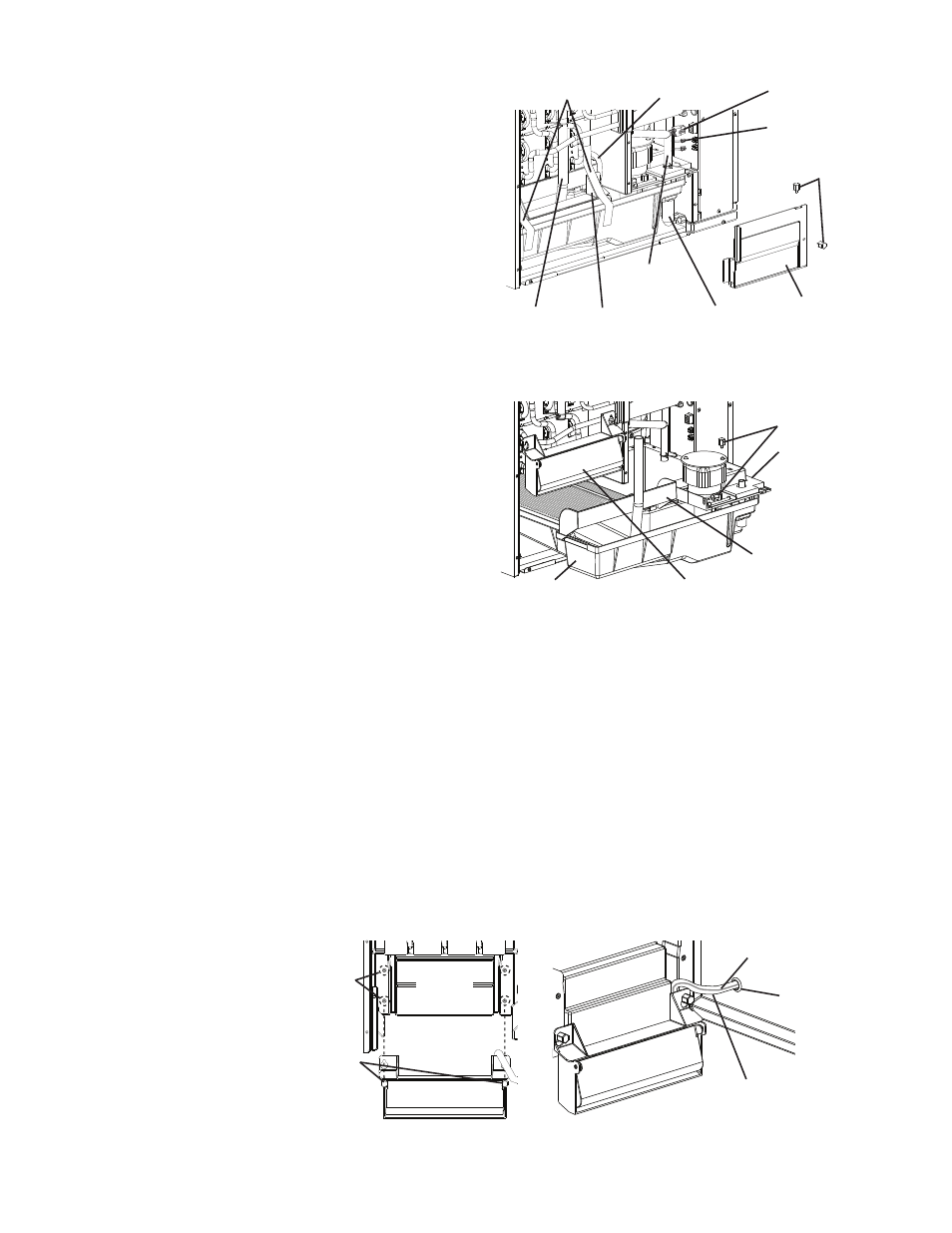
E. Bin Control Installation
1) Remove the 2 thumbscrews securing
insulation panel (B), then remove insulation
panel (B). See Fig. 3.
2) Disconnect the discharge hose, the drain
valve drain hose, and the overflow drain
hose.
3) Disconnect the pump motor connector and
the float switch connector from the side of
the control box.
4) Remove the tape securing the bin control.
5) Remove the 2 thumbscrews securing the
pump motor and float switch assembly.
See Fig. 4.
6)
Being careful not to pull the bin control
lead, lift the bin control up out of the water
tank. Being careful not to snag the bin
control or bin control lead, slide the water
tank, cube guide, and pump motor and
float switch assembly out of the icemaker.
Fig. 3
Fig. 4
Thumbscrews
Insulation
Panel (B)
Pump Motor
Connector
Float Switch
Connector
Drain Valve
Drain Hose
Overflow
Drain Hose
Discharge
Hose
Bin
Control
Tape
Thumbscrews
Water Tank
Cube Guide
Pump Motor
and Float
Switch
Assembly
Bin Control
Fig. 5
Bin Control
Thumbscrews
Rear
Interior
Wall
Use Upper or Lower
Set of Holes
Depending on
Application
Bin Control Lead
Vinyl Hose
Grommet
7) Secure the bin control to the rear interior wall using the 2 thumbscrews on the rear
interior wall and either the upper or lower set of mounting holes. For dispenser unit
applications, the lower set of holes is recommended. When installed on a standard
Hoshizaki storage bin, either set of holes is acceptable. Route the bin control lead vinyl
hose through the grommet as illustrated. Do not leave any slack in the ice drop zone.
See Fig. 5.
8) Replace the water tank, cube guide, and pump motor and float switch assembly in their
correct positions.
9) Secure the pump motor and float switch assembly with the 2 thumbscrews.
10) Reconnect the hoses.
Bin Control Lead