System configuration, 24 system configuration – Harman-Kardon AVR 510 User Manual
Page 24
24 SYSTEM CONFIGURATION
System Configuration
1. Make certain that all speaker positions
have been properly configured for their
“large” or “small” settings (as outlined
above) and turn off the OSD system if it is
in use.
2. Adjust the volume so that it is at -15, as
shown in the on-screen display or Main
Information Display
Y.
3. Hold the remote in front of you at arm’s
length, being sure not to cover the EzSet
Sensor Microphone
at the top of
the remote.
4. Press and hold the SPL Indicator Select
button
for three seconds. Release it
when the Program/SPL Indicator
c
stops flashing and you hear a test noise
from the front left speaker.
5. At this point, EzSet will take over, adjusting
the output level of each channel so that
when the process is complete all levels will
be equal and at the set reference point.
This process may take a few minutes,
depending on the extent of adjustment
required.
6. During the adjustment, you will see the
location of the channel position being
adjusted appear in both the on-screen
display (if connected) and the Main
Information Display
Y, alternating with
a readout of the output setting, relative to
the reference volume level. As the adjust-
ment proceeds, a few things will happen
simultaneously:
• The channel position being adjusted will
flash in the Speaker/Channel Input
Indicators
Q. If the test noise is heard
from a channel other than the one shown
in the Indicator, there is an error in the
speaker connections. If this is the case,
press the Test Button
i TWICE to
stop the adjustment. Then, turn the unit
off and verify that all speakers are con-
nected to the proper Outputs fi.
• When the front left channel is being set at
the beginning of the process, EzSet will
adjust the volume level, as shown by the
indication of the FRONT L LEV
alternating in the on-screen display (if
connected) and the Main Information
Display
Y with the volume indication.
During the adjustment, the test tone may
seem to pulse, or click, as EzSet changes
the level. This is a normal aspect of the
system’s operation.
• As the individual channels are set, the
channel name and the adjustment offset
will appear in the on-screen display (if
connected) and the Main Information
Display
Y. While the level is changing,
the Program/SPL Indicator
c will
change colors to reflect the output level
in relation to the reference. A red indica-
tion shows that the level is too high,
while an amber indication shows that the
level is too low. When the indicator is
green, the level is correct, and the test
noise will move to the next channel.
• While adjustments are being made, the
red LED under the AVR Selector
f
will flash. This is normal, and indicates
that EzSet is operating.
7. After the test noise has circulated once
through each channel, it will send the tone
to each channel once again, to verify the
settings.
8. After two complete circulations of the
tone, the levels are set. The Program/SPL
Indicator
c will remain green at each
channel. Upon completion of the second
circulation, the Program/SPL Indicator
c will flash green twice and then go out.
The tone will stop and the AVR 510 will
return to normal operation.
Manual Output Level Adjustment
Output levels may also be adjusted manually,
either to set them to a specific level with an
SPL meter, or to make fine tuning adjustments
to the levels obtained using the EzSet remote.
Manual output level adjustment is most easily
done through the OUTPUT ADJUST
menu (Figure 7). If you are already at the main
menu, press the
¤
button
n until the on-
screen
›
cursor is next to the OUTPUT
ADJUST line. If you are not at the main
menu, press the OSD button
v to bring up
the MASTER MENU (Figure 1), and then
press the
¤
button
n three times so that the
on-screen
›
cursor is next to the OUTPUT
ADJUST line. Press the Set button p to
bring the OUTPUT ADJUST menu
(Figure 7) to the screen.
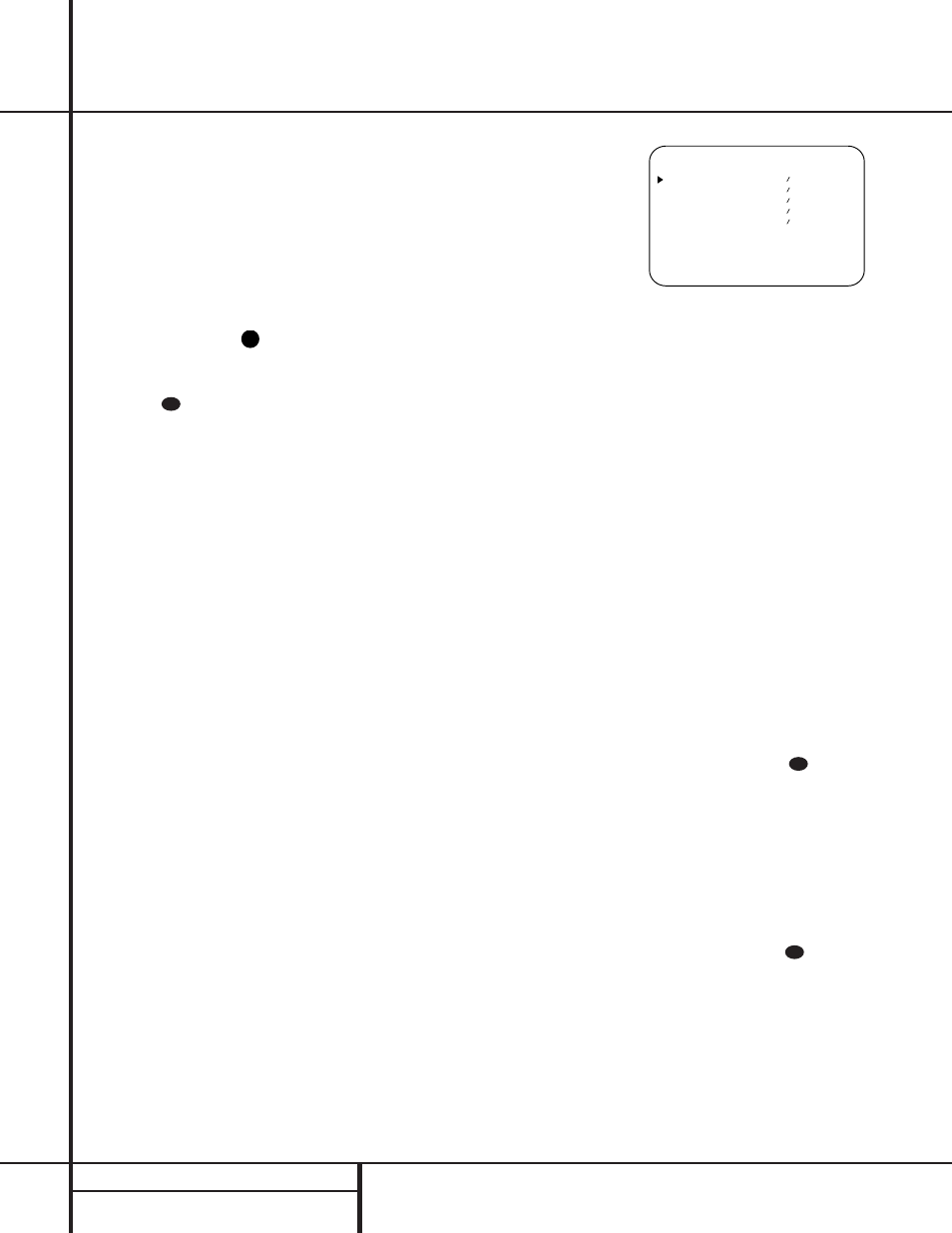
Figure 7
As soon as the new menu appears, you will
hear a test noise circulate from speaker to
speaker in a clockwise direction around the
room. The test noise will play for two seconds
in each speaker before circulating, and a blink-
ing on-screen cursor will appear next to the
name of each speaker location when the sound
is at that speaker.
NOTE: Remember to verify that the speakers
have been properly connected. As the test noise
circulates, listen to make certain that the sound
comes from the speaker position shown in the
Main Information Display
Y. If the sound
from a speaker location does NOT match the
position indicated in the display, turn the
AVR 510 off using the Main Power Switch
1 and check the speaker wiring to make cer-
tain that each speaker is connected to the cor-
rect output terminal.
After checking for speaker placement, let the
test noise circulate again, and listen to see
which channels sound louder than the others.
Using the front left speaker as a reference,
press the
‹
/
›
buttons
o
on the remote
to bring all speakers to the same volume level.
When one of the
‹
/
›
buttons is pushed, the
test noise circulation will pause on the channel
being adjusted to give you time to make the
adjustment. When you release the button, the
circulation will resume after five seconds.
Continue to adjust the individual channels until
the volume level sounds the same from each
speaker. Note that adjustments should be made
with the
‹
/
›
buttons
o
on the remote
only, NOT the main volume controls. If you are
using a sound-pressure level (SPL) meter for
precise level adjustment, set the volume so that
the meter reads 75dB, C-Weighting Slow.
31
31
* O U T P U T A D J U S T *
F R O N T L E F T : 0 d B
C E N T E R : 0 d B
F R O N T R I G H T : 0 d B
S U R R R I G H T : 0 d B
S U R R L E F T : 0 d B
R E T U R N T O M E N U
36
39