Harbor Freight Tools CENTRAL PNEUMATIC 94847 User Manual
Page 5
Page 5
SKU 94847
For technical questions, please call 1-800-444-3353
Caution: Do not turn on the Air Compressor at this time.
Oiler and Filter Connection
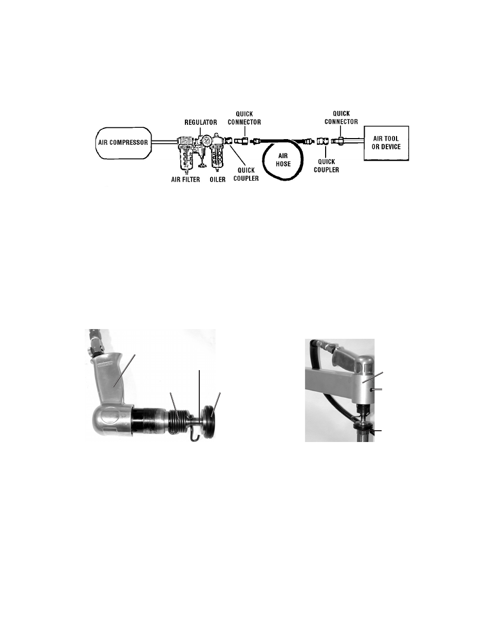
Dirt, water, and the lack of pneumatic tool oil are major causes for tool wear. Install an
optional oiler-filter (not supplied), as illustrated below for better performance.
Connect the air tool, air hoses, filter, and oiler to the Compressor Air Outlet as
illustrated below. Use pipe thread seal or Teflon tape on all threaded connections.
The filter and oiler (not supplied) are recommended but not mandatory for operation.
If the filter and oiler are not used, connect the air hose directly to the 1/4 inch, 18 NPT
connector located at the Air Switch Assembly Inlet (13) fitting. Also, a few drops of
pneumatic tool oil must be added through the air line before each use.
Mounting Air Hammer to “C” Frame
Unscrew Screw (2) so it is out of the way of the Air Hammer (10) when inserting it
into the “C” Frame. Do not remove Screw (2). See photo below, right.
Coil Spring
Hammer Head (3)
Hammer Sleeve (4)
Screw (2)
“C” Frame
Air Hammer (10)
Anvil (5)
Screw off the Coil Spring from the Air Hammer (10) and slip it off, along with the
Hammer Head (3) and Hammer Sleeve (4). See photo below, left.
Slide the Air Hammer body into the “C” Frame mounting hole as shown below, right.
Insert the desired size Anvil (5) onto the Adjustable Pole (7).
Place the Hammer Head (3) through the Coil Spring, then into the Air Hammer.
Screw on the Coil Spring until it stops.
Retighten Screw (2) completely.
1.
2.
3.
4.
5.
6.