Mower blade removal, Seat adjustment, Control lever adjustment – Hustler Turf Z4 User Manual
Page 29
9-6
602223_0609
Mower blade removal
Use a 15/16" wrench to remove the 5/8" cap screw holding the
blade to the spindle shaft from underneath. NOTE: A blade
holding tool (part number 381442) is available from Hustler
Turf Equipment. It is designed to prevent the blades from
rotating when they are being removed or installed on the
spindle. Contact your Hustler dealer for more information.
Sharpen the blades on a grinder following pattern as shown
(Figure 9-7). Touch-up sharpening can be done with a file.
Check the blades for balance following grinding. A
commercial balancing tool is available through most hardware
supply stores, or balancing can be done by placing the blade on
an inverted line punch or 1/2" bolt. Blade should not lean or tilt.
Spin the blade slowly, blade should not wobble. If blade is out
of balance, true it up before reinstalling.
Lay the blade on a flat surface and check for distortion
(Figure 9-8 & Figure 9-9). Replace any distorted blade.
Do not re-use spindle bolts which have stripped, worn or
undercut threads. Torque bolts on spindles to 118 foot-pounds
(160.0 nm) when reinstalling blades.
IMPORTANT: When mounting blades, rotate them after
installation to ensure blade tips do not touch each other or sides
of the mower.
WARNING: Failure to correctly torque the bolt may
result in the loss of the blade which can cause serious
injury.
WARNING: Mower blades are sharp and can cut.
Wrap the blade(s) or wear gloves and use extra caution
when servicing them.
Seat adjustment
There are two seat options available for this machine;
standard and suspension. The following are the adjustments for
each of these seats.
Standard seat
The standard seat has one adjustment; forward and rearward
travel. Figure 9-10
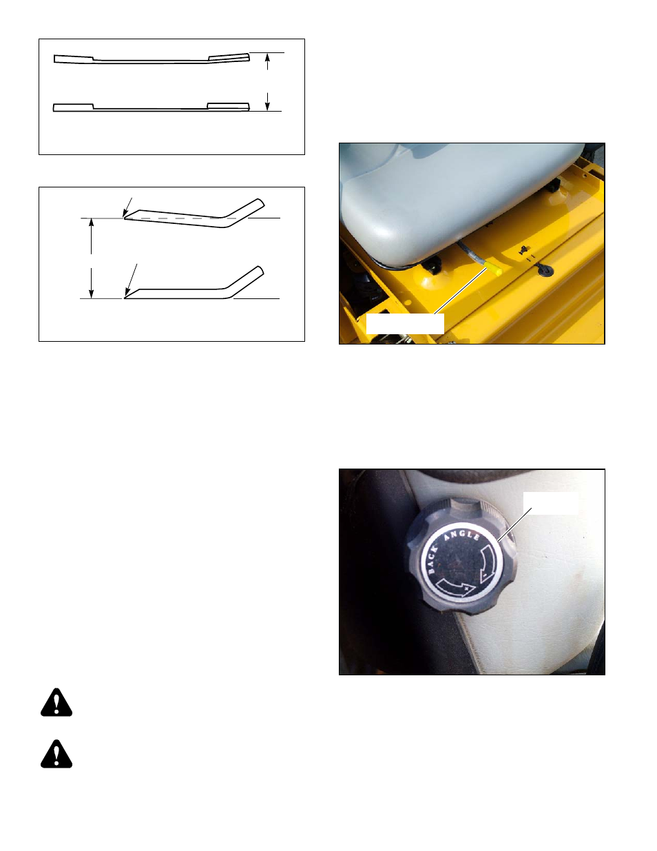
Suspension seat
The suspension seat can be adjusted four different ways to
obtain the most comfortable position:
1.
Back angle Figure 9-11
2.
Forward and rearward travel Figure 9-12
3.
Weight Figure 9-12
4.
Lumbar Figure 9-13
Control lever adjustment
The steering control levers can be adjusted for operator
comfort. By loosening the cap screws that attaches the upper
control lever to the lower lever (Figure 9-14), the upper control
lever can be pivoted to fit the operator’s personal preference.
The steering control levers should be adjusted so that they
align with each other when in the neutral position
Figure 9-8
Figure 9-9
Bladewrp.ai
Warped Blade (Replace)
Straight Blade
Cutting
plane
Comparison of Warped and Straight Blades
Bladetwt.ai
Cutting edge
Twisted Blade Edge
(replace)
Cutting edge
Cutting Plane
Straight Blade Edge
End view of blades, comparing
twisted and straightened blades
Figure 9-10
Figure 9-11
Forward/rearward
travel lever
Back angle
control