Service information ・・・・・・・・・・・・・・・・・・・71, Service information, Connector pin diagrams camera – Hitachi V-21W User Manual
Page 82
71
Service information
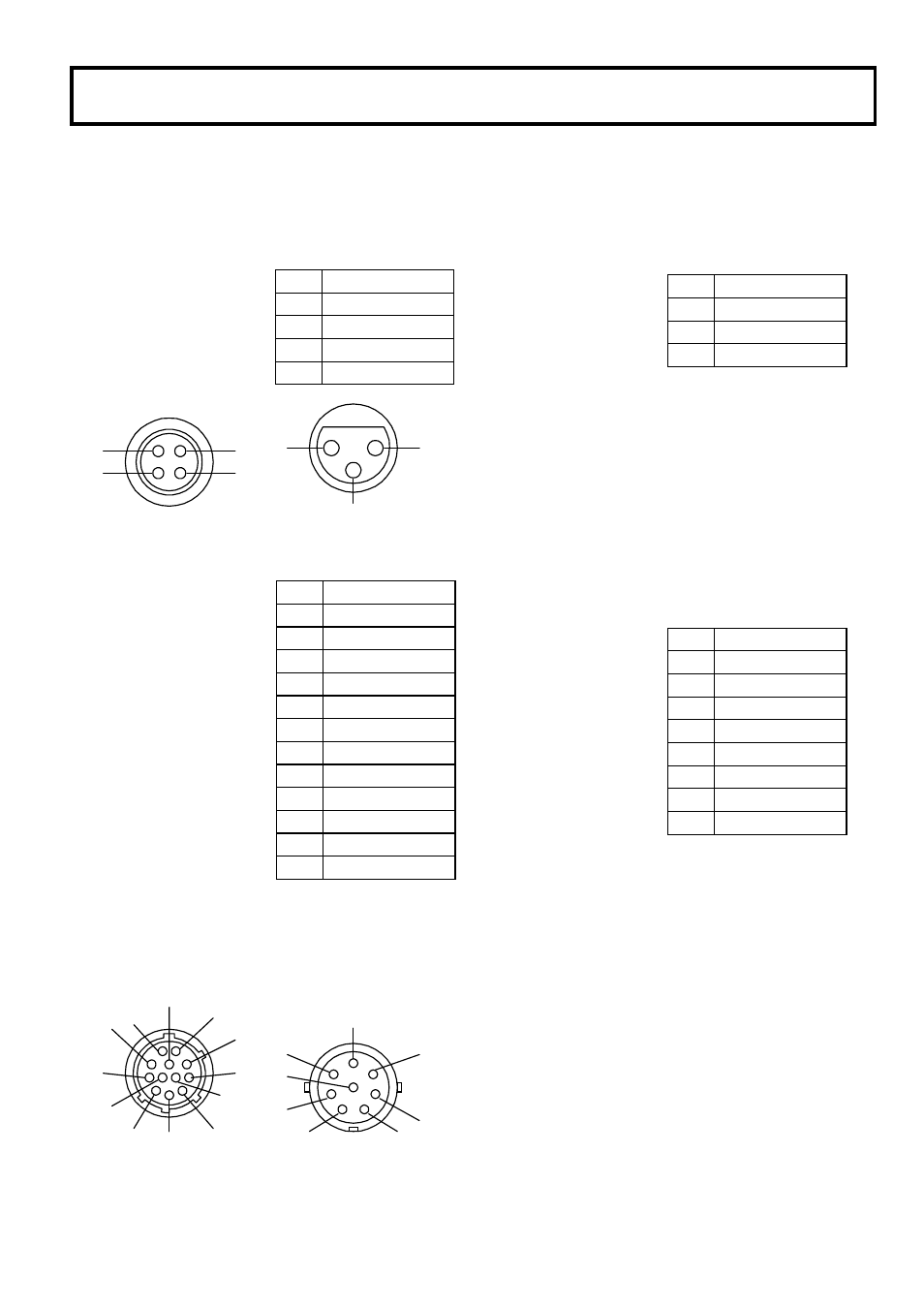
Connector pin diagrams
Camera
Remote (4 pin female)
MIC IN (3 pin female)
1
2
3
4
1
2
3
LENS (12 pin female)
VF (8 pin male)
1
2
3
4
11
5
7
12
6
8
9
10
C
B
H
E
F
D
A
G
Pin
Signal
1
+9V output
2
SD input
3
SD output
4
SD ground
Pin
Signal
1
MIC GND
2
MIC(H) IN
3
MIC(C) IN
Pin
Signal
1
AUX SW
2
CALL TRG
3
GND
4
ENF AUTO
5
IRIS CONTROL
6
+12V
7
IRIS POSITION
8
NC
9
NC
10
NC
11
NC
12
NC
Pin
Signal
A
B LED(C)
B
! LED
C
VF 9V
D
+12V
E
S LED
F
VF VIDEO(Y)
G
GND
H
T LED
This manual is related to the following products: