Tool set up, Safet y o pera tion m aintenan c e setup – Harbor Freight Tools 37793 User Manual
Page 9
Page 9
For technical questions, please call 1-800-444-3353.
Item 37793
SAFET
y
O
PERA
TION
M
AINTENAN
c
E
SETUP
Operating Instructions
Read the ENTIRE IMPORTANT SAFETy INFORMATION
yy
section at the beginning of this
manual including all text under subheadings therein before set up or use of this product.
Tool Set Up
TO PREVENT SERIOUS INJURy
TO PREVENT SERIOUS INJUR
TO PREVENT SERIOUS INJUR FROM A
yy
ccIDENTAL OPERATION:
Make sure that the Trigger is in the off-position and unplug the tool from its
electrical outlet before performing any procedure in this section.
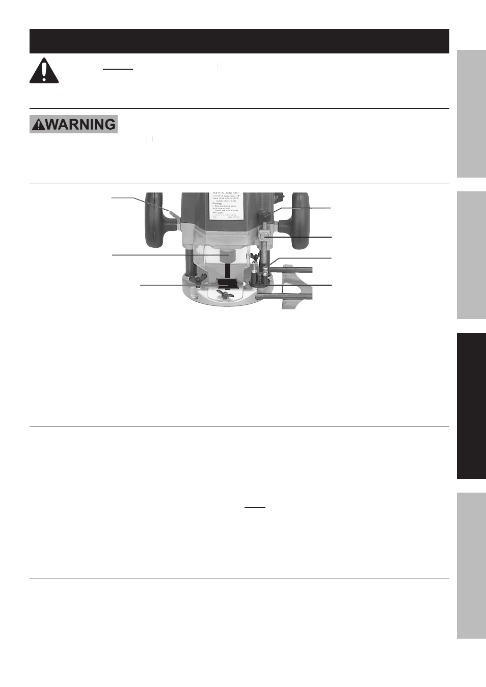
Installing Bits
Lock Lever (26)
Collet Nut (20)
Loosen to left
Tighten to right
Bit
Screw (32) Stopper
Pole
Hex Bolt (65)
Stopper (57)
Half Nut (18)
1. Push down on the shaft Lock Lever (26) to
keep the shaft stationary. See photo above.
2. Using Wrench (5A), loosen the Collet Nut (20).
3. Insert the bit all the way into the Collet Cone (21).
When using smaller shank bits, insert the
Collet Sleeve (2A) into the Collet Cone,
then the bit through the Cone.
4. Securely tighten Collet Nut (20).
Do not tighten the Collet Nut without inserting a bit or
Collet Cone with bit. Damage can occur.
5. Pull up the Lock Lever (26) to free the shaft.
cutting Depth Adjustment
1. Place the router on a flat surface.
2. Loosen the Lock Lever (26).
3. Lower router body until the bit just
touches the flat surface.
4. Tighten the Lock Lever.
5. Turn Stopper (57) turret to select the
desired Hex Bolt (65) height.
6. Lower the Screw (32) stopper pole until it touches the
adjustable Hex Bolt (65). Press and hold the Half Nut
(18) fast feed button to lower stopper pole rapidly.
7. Raise the Screw (32) stopper pole in fine increments
to desired depth of cut.
Note: The depth of cut is equal to the distance between
the end of the Screw (32) and the top of the Hex Bolt (65).
8. Loosen Lock Lever (26) and lower router body until
Screw (32) stopper pole makes contact with the
Hex Bolt (65). The depth of cut can now be seen.
Upper Limit Adjustment
The upper limit adjustment should be set so that the
bit clears the stock material by approximately 1/2 inch.
1. Turn the Knob (68) to the correct upper limit and clamp
in place using the Lock Lever (26).
2. Screw the Nut (70) down the screw shaft until it seats
firmly against the motor housing (5).
3. Loosen the Lock Lever.