Installation – Hunter Fan 43355 User Manual
Page 10
10
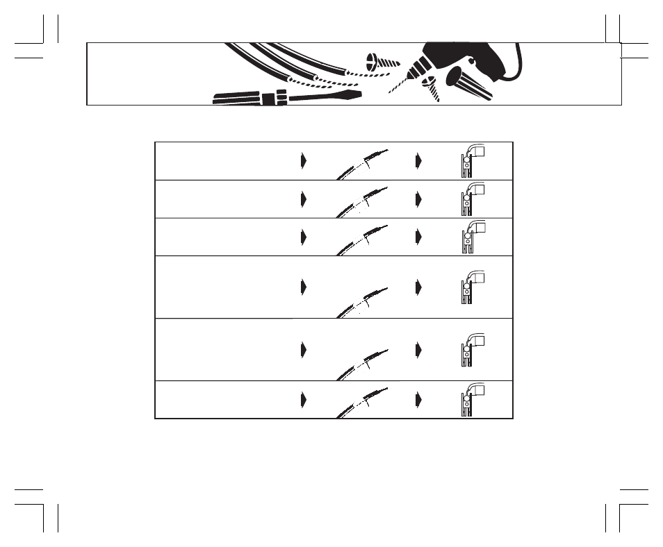
INSTALLATION
Table A
NOTE:
Do not connect a “Common” wire (sometimes labeled “C”) to any terminal on this thermostat.
Tape up the wire and do not use. This wire provides electricity to non-battery powered thermostats.
RH
G
RC
W/B
Y/O
Y1
RH, R, VR or 4
24 Volt
RC, VC
24 Volt Cool
G or F
Fan
Y, C or M
Air Conditioning Compressor
- or -
O
Reversing Valve operating in Cool mode.
(Single Stage Heat Pumps ONLY.)
If the code letter on your
existing thermostat is
then mark the wire
with label shown
and connect to thermostat
terminal shown
W or H
Heating
- or -
B
Reversing Valve operating in Heat mode.
(Single Stage Heat Pumps ONLY.)
Y1
Heat Pump compressor
(Single Stage Heat Pumps ONLY.)
x
RH
x
RC
x
G
x
Y/O
x
W/B
x
Y1
See also other documents in the category Hunter Fan Control panel:
- 44272 (2 pages)
- 47110A (2 pages)
- 47350A (23 pages)
- 44428 (22 pages)
- 40170 (33 pages)
- 47250A (7 pages)
- 44132 (2 pages)
- 42122 (25 pages)
- 44033-01 44277 (37 pages)
- 43154 (7 pages)
- SET & SAVE 44155C (52 pages)
- 44550 (38 pages)
- 40135 (30 pages)
- 43168 (21 pages)
- 44377W (64 pages)
- 44905 (54 pages)
- 42999 44050S (23 pages)
- 42710-01 (58 pages)
- 44050 (24 pages)
- 44008-01 (100 pages)
- 144860 (76 pages)
- 43255 (7 pages)
- 47550 (38 pages)
- 44660 (2 pages)
- 44377 (45 pages)
- 43057 (13 pages)
- 44459 (40 pages)
- PH20-30A (26 pages)
- 44665 (2 pages)
- 43157 (2 pages)
- 42711-01 (55 pages)
- 47300A (44 pages)
- 44760 (28 pages)
- 44110 (52 pages)
- 44127 (37 pages)
- 44260 (104 pages)
- 43665 (49 pages)
- 47200A (7 pages)
- 43153 (2 pages)
- 40120 (28 pages)