Harbor Freight Tools 42528 User Manual
Page 7
SKU 42528
Page 7
For technical questions, please call 1-800-444-3353.
Anytime
any maintenance or repairs are done (including clearing jams), FIRST:
1.
Disconnect the Nailer from the air hose.
2.
Empty the Magazine Unit (3-2) completely.
3.
Attempt to fire the Nailer into a piece of scrap wood to ensure that it is disconnected
and is incapable of firing any brads.
4.
Always leave the Magazine Side Cover (3-1) open during maintenance. The
Magazine is spring-loaded and may cause parts or a nail to fly out of the Nailer.
Clearing Jams
1.
Disconnect tool from air hose, empty the Magazine
Unit (3-2) of nails, release any built-up air pressure,
and leave the magazine open, as explained above.
2.
While doing this step and the next, hold the Nailer
pointed away from you and any other people or
fragile objects - see
Figure 2
. Loosen both Screws
(3-15) on the Driver Guide Cover A (3-10) 3/4 of a
turn each - see
Figure 3
.
3.
Slide the Driver Guide Cover A (3-10) toward the
nose of the Nailer slightly until the holes in the Driver
Guide Cover A (3-10) line up with the heads of both Screws (3-15).
4.
Carefully remove the Driver Guide Cover A (3-10) and
remove the jammed nail. Pliers may be necessary to
remove a stuck nail.
5.
Inspect the Driver Blade (3-18) for bends or breakage.
If it is damaged, do not use the tool until it is repaired by
a qualified technician.
6.
Lightly oil the Driver Blade (3-18) and replace the Driver
Guide Cover A (3-10). Slide the Driver Guide Cover A
(3-10) away from the nose of the Nailer until the shafts
of the Screws (3-15) fit into the slots in the cover. Tighten
all Screws (3-15) securely.
7.
Reload the Nailer.
8.
Reconnect the Nailer to the air hose.
9.
Press the Nose Piece (3-11) of the Nailer against an
appropriate piece of scrap wood.
10.
Test fire the Nailer several times, checking for proper
operation.
11.
Disconnect the Nailer, remove the nails and store
Nailer in a location out of children’s reach.
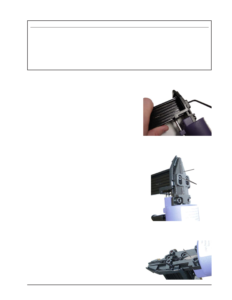
FIGURE 2
FIGURE 3
Screw
(3-15)
Driver Guide
Cover A
(3-10)
FIGURE 4
Driver Blade
(3-18)