Harbor Freight Tools Foldable Utility Trailer 90154 User Manual
Page 8
Page 8
For technical questions, please call 1-800-444-3353.
Item 90154
SAFET
y
Op
ERA
TION
M
AINTENAN
c
E
A
SSEM
b
Ly
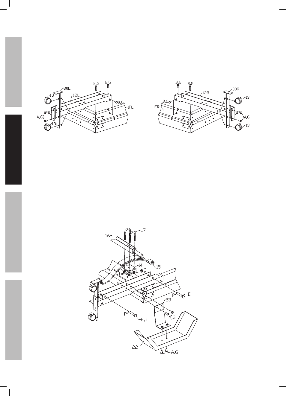
9. With the Trailer in its folded position, attach the
Spring Hanger (12L) to the Front Left Side Rail (1FL),
using 3/8″ x 1″ Bolts (B) and 3/8″ Lock Nuts (G).
Attach the Spring Hanger (12R) to the
Front Right Side
Rail (1FR), using 3/8″ x 1″ Bolts (B)
and 3/8″ Lock Nuts (G).
(See Figure F.)
10. Attach the Caster Base (30L) to the
Spring Hanger (12L), using 3/8″ x 1″ Bolts (B)
and 3/8″ Lock Nuts (G).
11. Attach the Caster Base (30R) to the
Spring Hanger (12R), using 3/8″ x 1″ Bolts (A)
and 3/8″ Lock Nuts (G).
12. Attach the Casters (13) to the
two Caster Bases (30L, 30R),
using M12 Lock Nuts (U).
Left casters
Right casters
Figure F: caster Assembly
13. Attach the two Fender Supports (23) to the
two Caster Bases (30L, 30R), using the 3/8″ Bolts (A)
and 3/8″ Lock Nuts (G).
Then attach the two Fenders (22) to the
two Fender Supports, using the 3/8″ Bolts (A)
and 3/8″ Lock Nuts (G).
(See Figure G.)
14. Attach the two Springs (15) to the
two Caster Bases (30L, 30R), using
9/16″ x 3‑1/4″ Bolts (E) and 9/16″ Nuts (I).
Leave these Bolts loose for now to
allow proper assembly in the next steps.
Insert a Cotter Pin (P) through the holes in the
end of the Bolts and spread the Cotter Pins.
15. Align the guide pin at end of axles through the
Springs (15). Position the two Spring Plates (14)
under the two Springs. Axle guide pins must be
located in the center hole of the Spring Plates (14).
16. On each end of the Axle, insert two U-Bolts (17)
downward over the Axle and through the
mounting holes in each of the two Spring Plates.
Adjust the Spring Plates slightly to
allow the holes to line up.
17. Then secure the Axle and Spring assemblies,
using 3/8″ Spring Washers (L) and
3/8″ Lock Nuts (G). After doing this, tighten the
Bolts (E) and Nuts (I) left loose in step 14.
Figure G: Spring Assembly