Tsurumi TPG-2900H-DX User Manual
Page 61
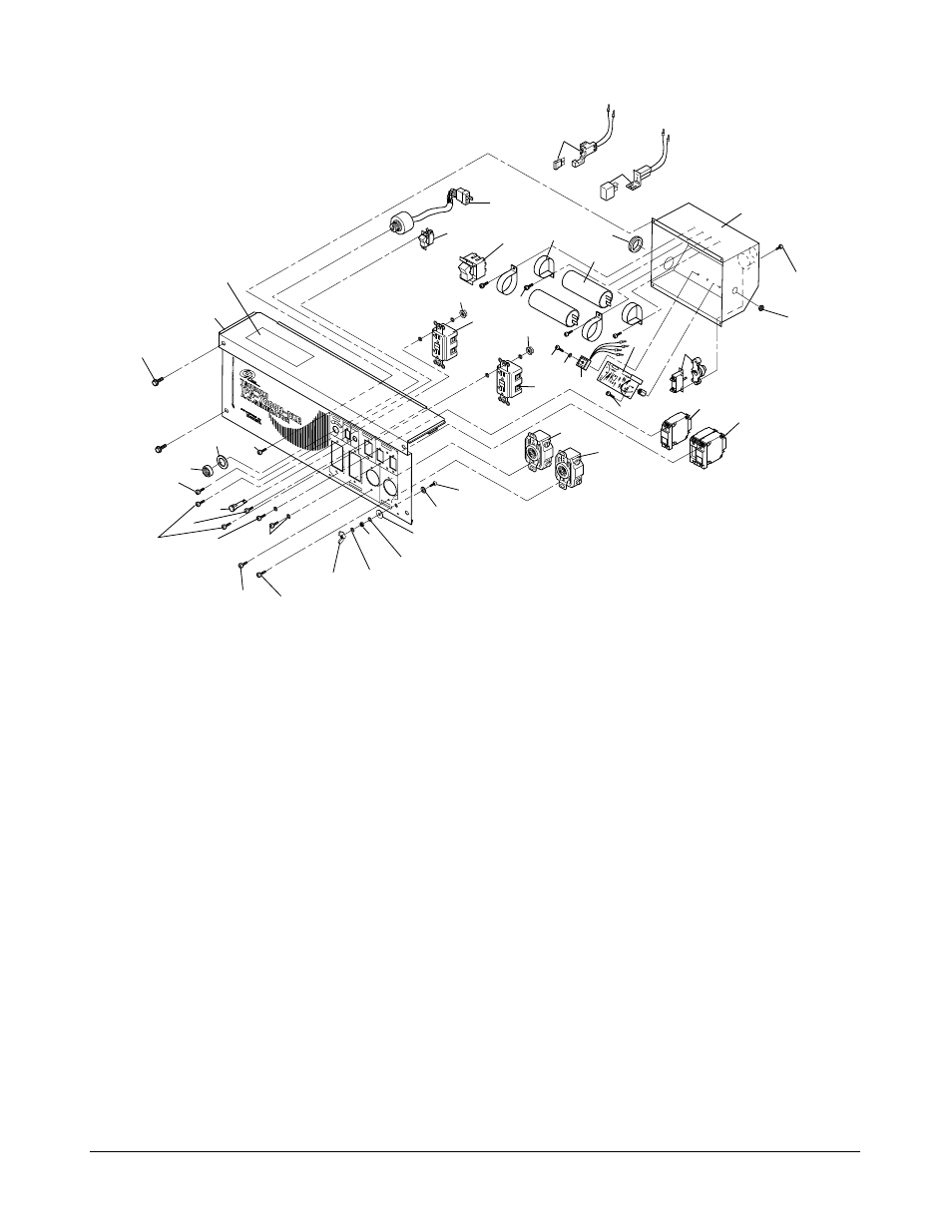
Figure 35: Front Panel and Control Box Components
(Model TPG-7000H-DXE Shown)
(3) Overload Protector (TPG-7000H-DXE)
(a) Refer to Figure 35. Remove front panel (29) and control box (32) (refer to
Removal/Installation of Front Panel and Control Box).
(b) Remove overload protector (H-33) from its connector.
(c)
Install replacement overload protector (H-33) in its connector.
(d) Install front panel (29) and control box (32) (refer to Removal/Installation of Front
Panel and Control Box).
(4) DC Fuse (TPG-7000H-DXE)
(a) Refer to Figure 35. Remove front panel (29) and control box (32) (refer to
Removal/Installation of Front Panel and Control Box).
(b) Remove fuse (H-32) from its fuse holder.
(c)
Install replacement fuse (H-32) in its fuse holder.
(d) Install front panel (29) and control box (32) (refer to Removal/Installation of Front
Panel and Control Box).
Removal/Installation
Page 58
Tsurumi’s Operation, Service, and Repair Manual
H-32
H-33
72
32,33
H-31
H-27
38
40
42
42
64
65
63
43
43
66
67
68
69
70
H-30
51
54
47
49
57
58
59
60
61
62
58
30
30.1
31
34
H-28
H-29
39
45
46
41
52,53 55,56
48
50
72.1