Assembly step 2, Assembly step – Horizon Fitness EX-67 User Manual
Page 5
BEFORE
YOU
BEGIN
INTRODUCTION
IMPORT
ANT
PRECAUTIONS
ASSEMBL
Y
BEFORE
YOU
BEGIN
ELLIPTICAL
OPERA
TION
LIMITED
W
ARRANTY
TROUBLESHOOTING
&
MAINTENANCE
CONDITIONING
GUIDELINES
BEFORE YOU
BEGIN
ASSEMBL
Y
INTRODUCTION
IMPORT
ANT
PRECAUTIONS
ELLIPTICAL OPERA
TION
CONDITIONING GUIDELINES
TROUBLESHOOTING &
MAINTENANCE
LIMITED WARRANTY
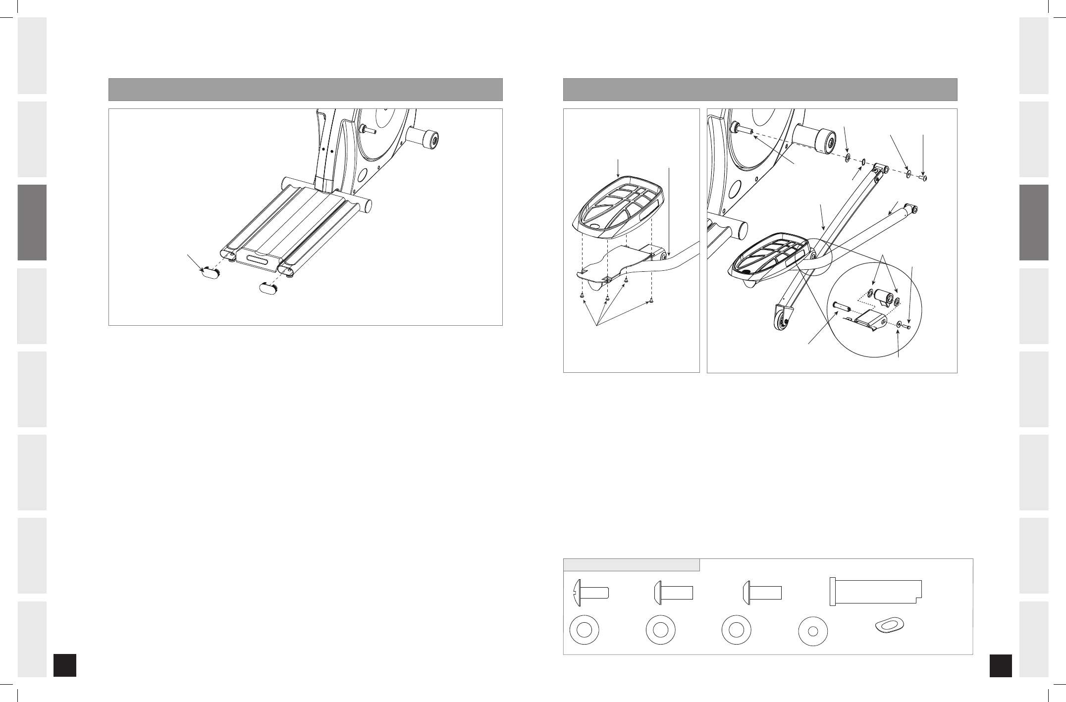
ASSEMBLY STEP 2
GUIDE RAIL CAPS
NOTE: There is NO hardware bag for this step.
A) Slide
GUIDE RAIL CAPS into the GUIDE RAIL to seal the openings.
WAVY WASHER (D)
CRANK
BOLT (G)
WASHER (I)
WASHER (H)
RIGHT PEDAL ARM
RIGHT LOWER LINK ARM
WASHERS (S)
SPACER (R)
BOLT (T)
WASHER (U)
FOOTPAD
LINK ARM
SCREWS (F)
ASSEMBLY STEP
WAVY WASHER (D)
CRANK
BOLT (G)
WASHER (I)
WASHER (H)
RIGHT PEDAL ARM
RIGHT LOWER LINK ARM
WASHERS (S)
SPACER (R)
BOLT (T)
WASHER (U)
FOOTPAD
LINK ARM
SCREWS (F)
A) Open
HARDWARE BAG FOR STEP 3.
B) Attach
FOOTPAD to PEDAL ARM using 4 SCREWS (F).
C) Align the bracket on the RIGHT LOWER LINK ARM with the tube on the RIGHT PEDAL ARM.
D) Slide the SPACER (R) through the LINK ARM BRACKET and the PEDAL ARM so it can’t rotate.
E) Insert 2
WASHERS (S) between the PEDAL ARM and the LINK ARM BRACKET.
F) Secure the joint with a FLAT WASHER (U) and BOLT (T).
G) Attach
PEDAL ARM to the CRANK with 1 BOLT (G), 1 WASHER (I), 1 WAVY WASHER (D) and 1 WASHER (H).
H) Repeat on other side.
SCREW (F)
12 mm
Qty: 8
BOLT (G)
13 mm
Qty: 2
BOLT (T)
15 mm
Qty: 2
SPACER (R)
70 mm
Qty: 2
WASHER (H)
Qty: 2
WASHER (U)
35 mm
Qty: 2
WASHER (S)
30 mm
Qty: 4
WASHER (I)
Qty: 2
WAVY WASHER (D)
Qty: 2
angle view
HARDWARE BAG FOR STEP CONTENTS :
EX-67_Rev.1.6.indd 8-9
7/7/08 4:29:13 PM