Framing and clearances, Warning, Danger – Heat & Glo Fireplace HEAT & GLO CF550E-B User Manual
Page 7
Heat & Glo • CRESTFIRE Series Electric Fireplace • 4030-781 Rev F • 10/06
7
3
3
Framing and Clearances
A. Selecting Heater Location
Several options are available to you when choosing a loca-
tion for your heater. This heater may be used as a room
divider, installed along a wall, across a corner or used in an
exterior chase. See Figure 3.1. This heater may be installed
directly on the fl oor, carpet or raised on a hearth.
Fire Risk
Provide adequate clearances.
• Around air openings
• To
combustibles
• For service access.
Locate heater away from traffi c areas.
WARNING
B. Clearances
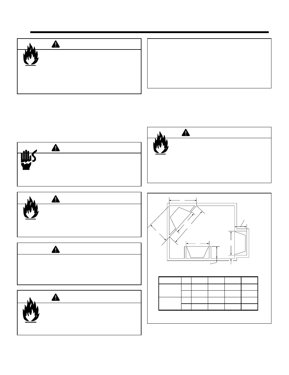
Figure 3.1 shows all clearances that must be maintained
around the heater.
Fire Risk
Due to high temperature, this heater should
be located out of high traffi c areas.
• Keep combustible materials such as
furniture, pillows, bedding, papers,
clothes and curtains at least 12 in.
(305 mm) from the front of the heater.
WARNING
Electrocution Risk
• NEVER locate this heater where it may fall
into a bathtub or other water container.
• Contact local building administrator for
information on bathroom intallations.
DANGER
Fire Risk!
• Prevent contact with sagging, loose
insulation.
• Do NOT install against vapor barriers or
exposed insulation.
WARNING
Do NOT use this heater if any part has been under water.
Immediately call a qualifi ed service technician to inspect
the heater and to replace any part of the control system
which has been under water.
WARNING
D
B
A
1 in. (26 mm) min.
14 in.
(356 mm)
14 in.
(356 mm)
A
A
C
Figure 3.1 Heater Locations
Fire Risk
• Comply with all minimum clearances to
combustibles as specifi ed.
Failure to comply may cause fi re.
WARNING
Note: Minimum and maximum clearances must be
maintained at all times. Illustrations throughout these
instructions refl ect typical installations and are for design
purposes only. Actual installation may vary slightly due to
individual design preferences.
The illustrations and diagrams used throughout these
installation instructions are not drawn to scale.
Model
A
B
C
D
CF550E-B
Series
in.
36-1/4
45
22-1/2
31-7/8
mm
921
1143
572
810
CF750E-B
Series
in.
41-1/8
50
25
35-3/8
mm
1045
1270
635
899