Honeywell W7620 User Manual
Page 9
r
I
If securing screws are not used, the
expansion board will not be grounded. This
will result in improper operation or damage to
t h e device.
N O T E
I
The W7620 Single Zone Application Guide, Form
63-4220,
provides information on corresponding terminal
designations to function connections. Verify that the
wiring was done according to the wiring diagram provided
and the J/O Control Function Cross-Reference provided
on the inside cover of the W7620.
Wire as follows:
1. strip
inch (5 mm) insulation from the
conductor.
2. Insert the wire in the required terminal location
and tighten screw terminal.
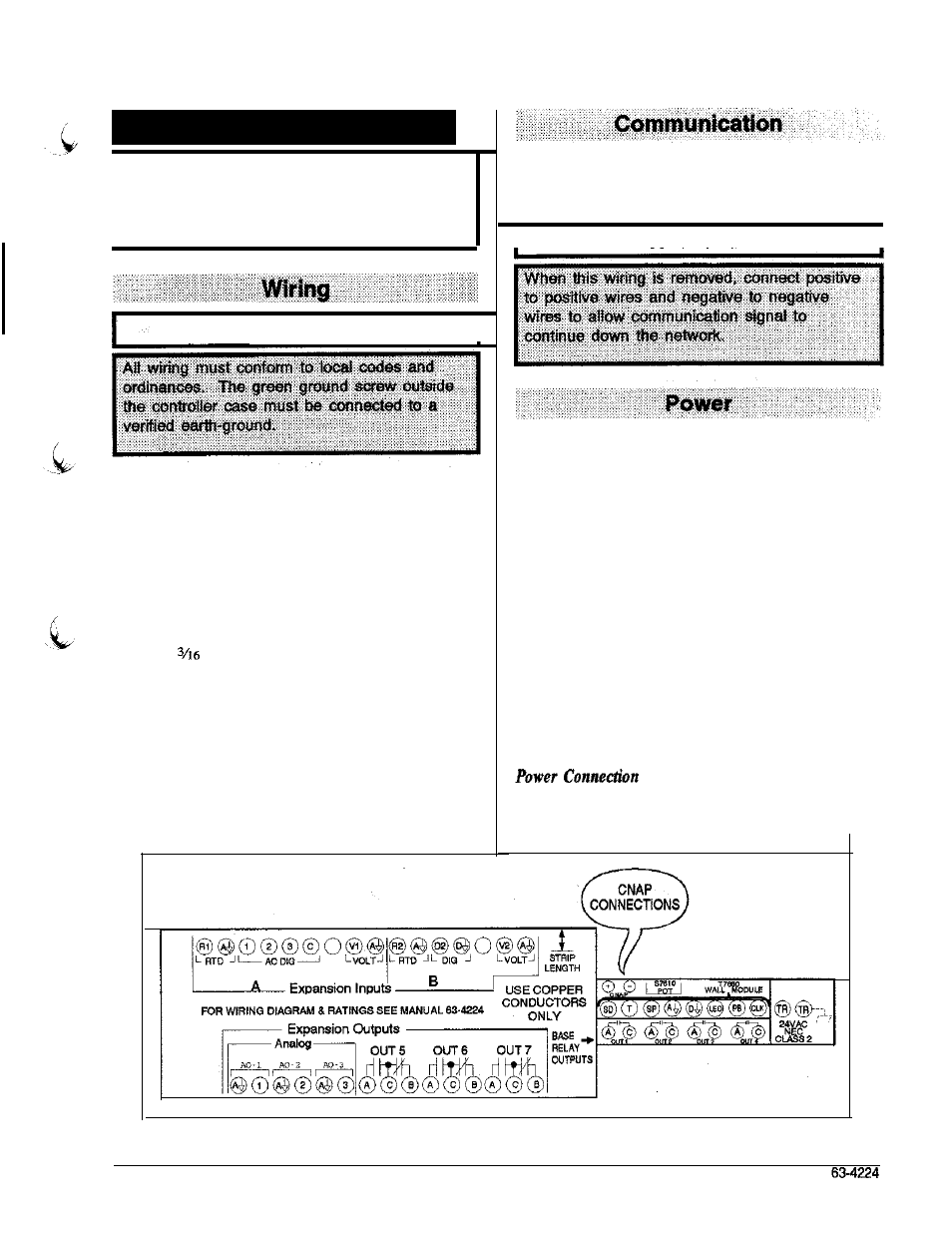
Figure 6 illustrates the terminal arrangement in the
controller. All controller models are furnished with a
terminal arrangement similar to that shown in this figure.
Pull the pair of CNAP communication cables to each
controller on the network and connect to the screw
terminals marked CNAP +/- (Figure 6).
I
N O T E
I
Power Wire Lengths
1. Power requircmcnts limit 24 Vac power
transmission distance. The following data can be
used in calculating load versus wire length:
Device
V
A
W7620
3.9
output relay
0.5
Analog output
0.6
Power relay
4-10
2.
The power relay load rating depends on the relay
used. Power relays can be wired to draw coil
current from separate 24 Vac supply.
3.
The operating voltage range for the W7620 is 20
to 30 Vac.
Pull a pair of 24 Vac power cables from either an isolated
or shared transformer to each controller on the n e t work
ml connect to Terminals TR and TR earth-ground.
Figure 6 -Terminal Designation Label