Pre-assembly, Assembly step 1, Assembly step 2 – Horizon Fitness 1.3T User Manual
Page 5: Assembly step 3, You’re finished, Warning, Do not cut straps until step 1-e, Ab c d e
INTRODUCTION
IMPORT
ANT
PRECAUTIONS
ASSEMBL
Y
BEFORE
YOU
BEGIN
TREADMILL
OPERA
TION
LIMITED
W
ARRANTY
TROUBLESHOOTING
&
MAINTENANCE
CONDITIONING
GUIDELINES
INTRODUCTION
IMPORT
ANT
PRECAUTIONS
ASSEMBL
Y
BEFORE YOU
BEGIN
TREADMILL OPERA
TION
CONDITIONING GUIDELINES
TROUBLESHOOTING &
MAINTENANCE
LIMITED WARRANTY
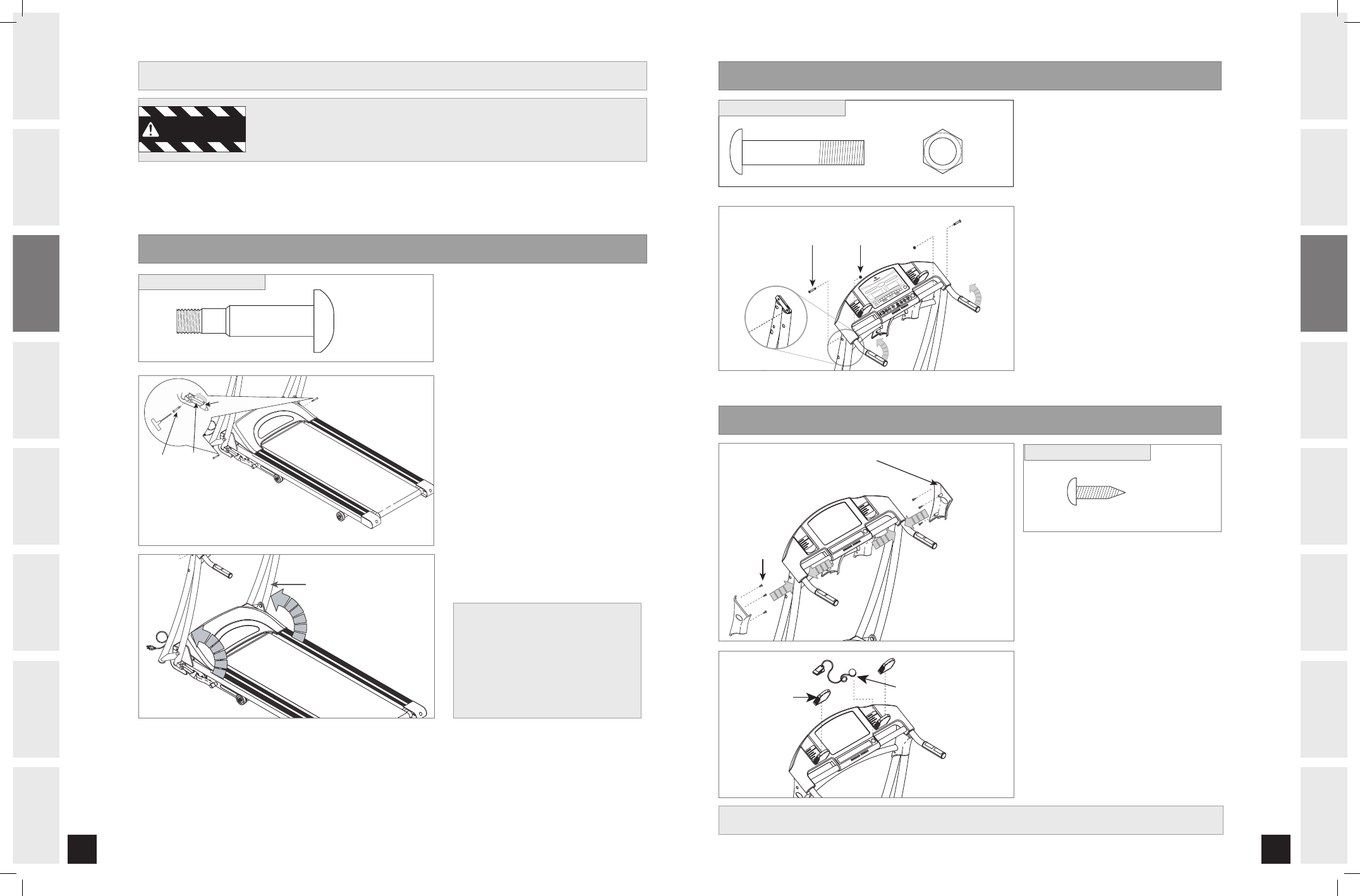
DO NOT CUT STRAPS UNTIL STEP 1-E!*
Disassemble box and remove the
cardboard packaging that is not beneath the treadmill. Do not attempt to lift the
treadmill at this time. Remove plastic wrap from console masts.
Open HARDWARE BAG 1.
Lift LEFT CONSOLE MAST into
upright position. Be sure to hold
the console mast firmly, as it
will not stay in the upright
position on it’s own.
Move LEFT SIDE LINKAGE ARM
into position. Insert BOLT (A)
and tighten.
Repeat on the right side.
Now cut the banding straps and
remove remaining packaging
material.*
PRE-ASSEMBLY
WARNING
ASSEMBLY STEP 1
A
B
C
D
E
BOLT (A)
45 mm
Qty: 2
HARDWARE BAG 1 CONTENTS :
BOLT (A) LOWER
LINKAGE
ARM
BOLT (B)
NUT (C)
LINK ARM COVER
TIM
E
DIS
TAN
CE
CAL
OR
IES
PU
LSE
INC
LIN
E
SPE
ED
1MP
H
2MP
H
3MP
H
4MP
H
5MP
H
6MP
H
7MP
H
8MP
H
9MP
H
10
MPH
PRE
SS
ENT
ER
TO
SET
SPE
ED
MAG
NETI
C K
EY
1.3T
INC
LIN
E
SPE
ED
INC
LIN
E
%
SPE
ED
MP
H
STO
P
HOL
D T
O R
ESE
T
STA
RT
QUI
CK
STA
RT
ENT
ER
CHA
NGE
DIS
PLA
Y
1 2
3 4
5 6
7 8
9 1
0
1 2
3 4
5 6
7 8
9 1
0
ASSEMBLY STEP 2
BOLT (A) LOWER
LINKAGE
ARM
BOLT (B)
NUT (C)
LINK ARM COVER
TIM
E
DIS
TAN
CE
CAL
OR
IES
PU
LSE
INC
LIN
E
SPE
ED
1MPH
2MPH
3MPH
4MP
H
5MPH
6MP
H
7MP
H
8MPH
9MPH
10
MPH
PRE
SS
ENT
ER
TO
SET
SPE
ED
MAG
NETI
C K
EY
1.3T
INC
LIN
E
SPE
ED
INC
LIN
E
%
SPE
ED
MP
H
STO
P
HOL
D T
O R
ESE
T
STA
RT
QUI
CK
STA
RT
ENT
ER
CHA
NGE
DIS
PLA
Y
1 2
3 4
5 6
7 8
9 1
0
1 2
3 4
5 6
7 8
9 1
0
#0-5 #
NN
2UZ
/:-0/
/65 $
NN
2UZ
HARDWARE BAG 2 CONTENTS :
Open HARDWARE BAG 2.
Lift CONSOLE (as shown) to lock
it into place.
Insert BOLT (B) through
CONSOLE MAST and secure
using NUT (C).
Repeat on other side.
Note: Do not pinch the wires.
A
B
C
D
$0/40-&."45
* NOTE: If the straps have been removed
before completing step 1-D and the
linkage arms cannot be aligned, refer
to the TROUBLESHOOTING section
(page 35) in order to restore the
treadmill to its proper position.
ASSEMBLY STEP 3
BOLT (D)
CONSOLE MAST COVER
BOLT (D)
16 mm
Qty: 6
HARDWARE BAG 3 CONTENTS :
WATERBOTTLE
HOLDER
SAFETY KEY
Open HARDWARE BAG 3.
Place CONSOLE MAST COVERS
over CONSOLE MASTS as shown.
Attach CONSOLE MAST COVERS
using 6 BOLTS (D).
Place WATER BOTTLE HOLDERS
and SAFETY KEY into the correct
positions. It is now safe to plug
in your treadmill.
A
B
C
D
YOU’RE FINISHED!
1.3T_Rev.1.4.indd 8-9
7/12/06 8:25:07 AM