HP H2H3 User Manual
Page 16
INSTALLATION INSTRUCTIONS
3-phase R-22 Split System Heat Pump
16
506 01 5001 00
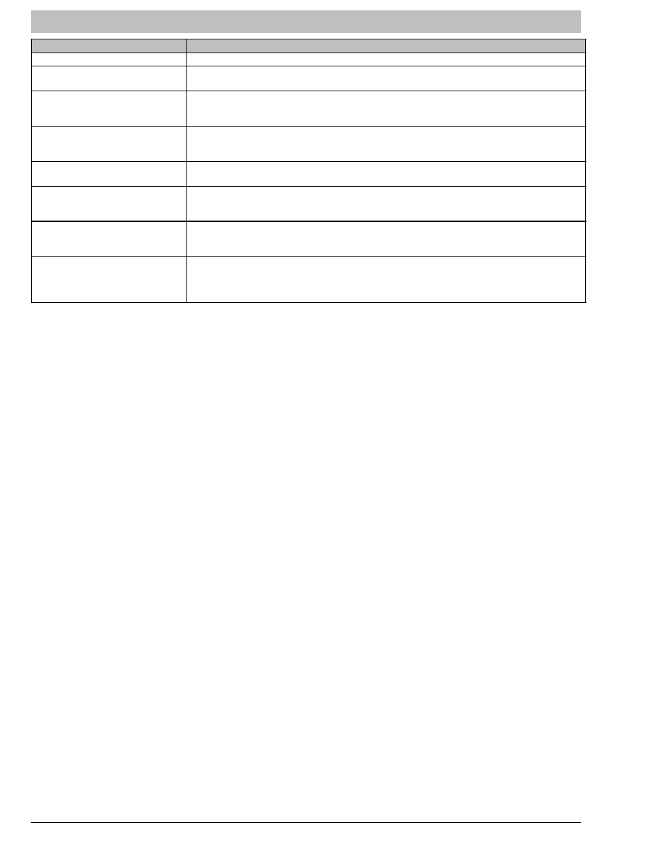
Figure 19
Comfort Alert
t Diagnostics (some models)
Miswired Module Indication
Troubleshooting Information
Green LED is not on, module
does not power up
Determine if both R and C module terminals are connected. Verify voltage is
present at module's R and C terminals.
Green LED intermittent, mod‐
ule powers up only when com‐
pressor runs
Determine if R and Y terminals are wired in reverse. Verify module's R and C
terminals have a constant source.
TRIP LED is on but system
and compressor check OK
Verify Y terminal is wired properly per OEM wiring diagram. Verify voltage at
contactor coil falls below 0.5VAC when off. Verify 24VAC is present across Y and
C when thermostat demand signal is present. If not, R and C are reverse wired.
TRIP LED and ALERT LED
flashing together
Verify R and C terminals are supplied with 19-28VAC.
ALERT Flash Code 3
(Compressor short cycling)
displayed incorrectly
Verify Y terminal is connected to 24VAC at contactor coil. Verify voltage at
contactor coil falls below 0.5VAC when off.
ALERT Flash Code 5 or 6
(Open Circuit, Missing Phase)
displayed incorrectly
Check that compressor T1 and T3 wires are through module's current sensing
holes. Verify Y terminal is connected to 24VAC at contactor coil. Verify voltage at
contactor coil falls below 0.5VAC when off.
ALERT Flash Code 8
(Welded Contactor) displayed
incorrectly
Determine if module's Y terminal is connected. Verify Y terminal is connected to
24VAC at contactor coil. Verify 24VAC is present across Y and C when
thermostat demand signal is present. If not, R and C are reversed wired. Verify
voltage at contactor coil falls below 0.5VAC when off. Review.
International Comfort Products, LLC
Lewisburg, TN 37091