Operation, Controls – Hustler Turf 4300 User Manual
Page 13
728444 Rev. 11/02
3-1
Controls
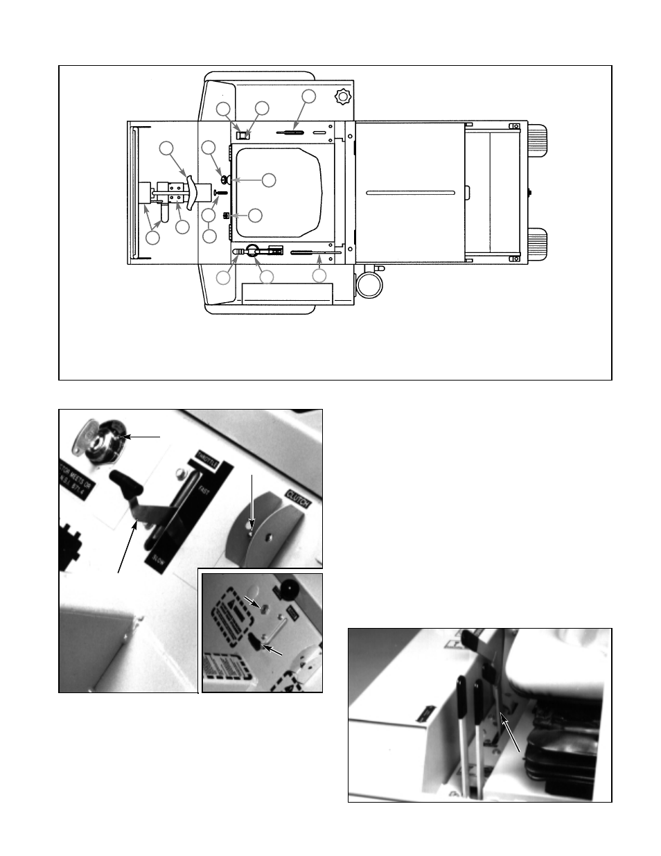
For general location of the controls described in this
section, refer to Figure 3-1.
1. Ignition switch (Fig. 3-2) – Models 4200,4400, 4420
and 4600. A four-position switch: off, pre-heat, run
and start. With key inserted, rotate it counterclock-
wise for engine pre-heat, then rotate full clockwise for
start; release key when engine fires, and switch will
automatically return to RUN position.
Models 4300 and 4500. A three-position switch: off,
run and start. With key inserted, rotate it clockwise to
start. Release key when engine fires, and switch will
automatically return to RUN position.
2. Throttle (Figs. 3-2 and 3-3) – a mechanical link
connected to the engine governor for controlling
engine rpm. On models 4200/4400/4420/4600 (Fig. 3-
2), move lever up to increase engine rpm, move down
to decrease engine rpm. On models 4300 and 4500
(Fig. 3-3), move lever down and forward to increase
engine rpm, pull up and back to decrease engine rpm.
3. Choke control (Fig. 3-2) – a cable link to manual
engine choke, models 4300 and 4500 only. Move up
for cold starting, move down for normal run.
OPERATION
Figure 3-1
Figure 3-2
Figure 3-3
T
Th
hrro
ottttlle
e lle
ev
ve
err
((M
Mo
od
de
ells
s 4
43
30
00
0 &
& 4
45
50
00
0
o
on
nlly
y))
Ignition Switch
Throttle
Lever
(Models 4200 & 4400)
(Models 4420 & 4600 not
shown)
Electric Clutch
Switch
1. Ignition Switch
4. Electric Clutch Switch
8. Parking Brake
12. Warning Lights
2a. Throttle Lever (4200, 4400 4420 & 4600)
5. Neutral Lock Levers
9. Attachment Lift Lever
13. Seat Latch
2b. Throttle Lever (4300 & 4500)
6. Steering Control Lever
10. Auxiliary Control Lever
3. Choke Lever (4300 & 4500 only)
7. Pump Clutch Lever
11. Hour Meter
1
2a
3
13
4
9
10
2b
8
11
7
5
12
6
IIg
gn
niittiio
on
n
S
Sw
wiittc
ch
h
C
Ch
ho
ok
ke
e
L
Le
ev
ve
err
((M
Mo
od
de
ells
s
4
43
30
00
0 &
&
4
45
50
00
0))