Remote control wiring diagrams – Hearth and Home Technologies RCT-MLT-II User Manual
Page 11
11
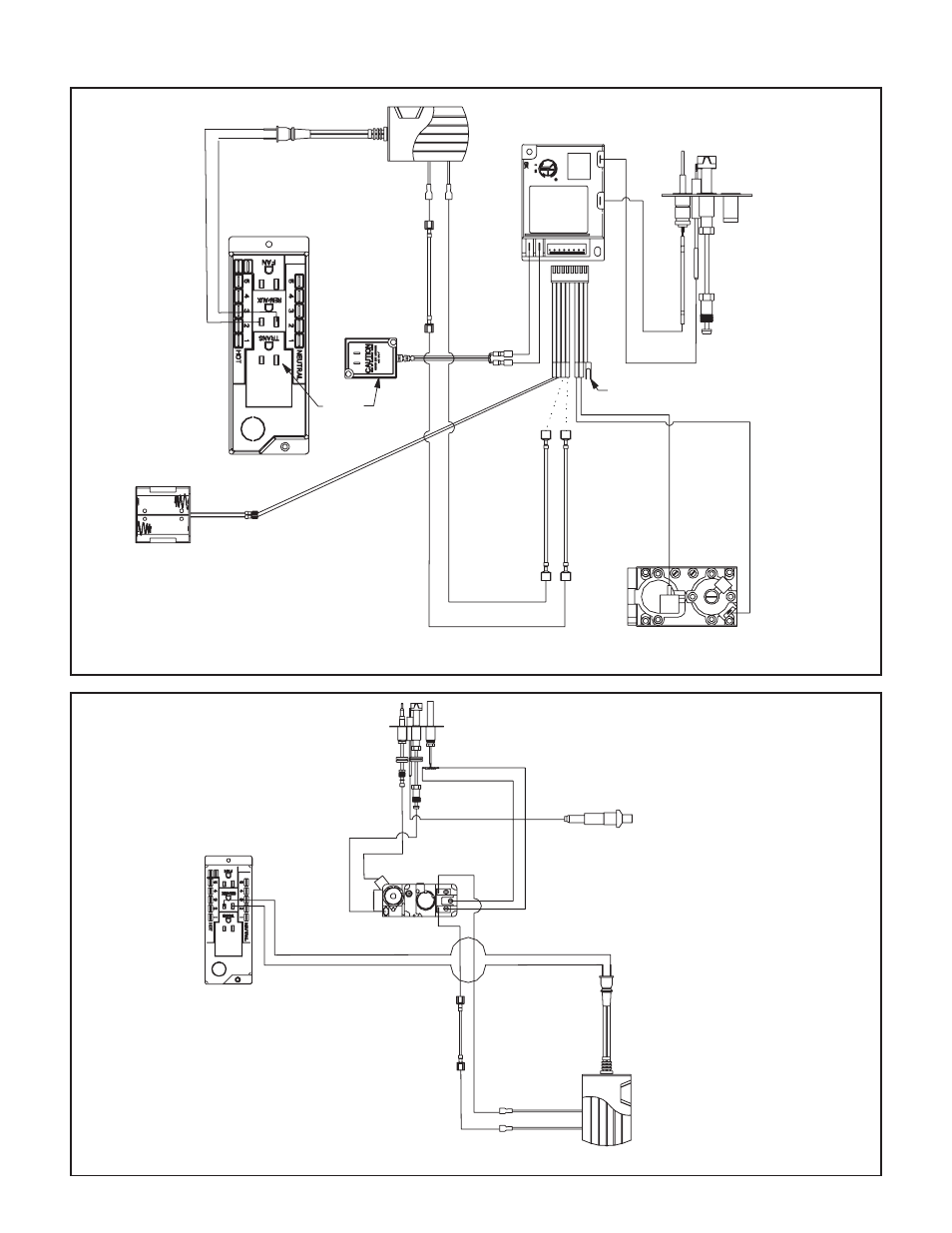
Figure 14. Remote Control Standing Pilot Ignition Wiring Diagram
Figure 13. Remote Control Intermittent Pilot Ignition (IPI) Wiring Diagram
Remote Control Wiring Diagrams
VALVE
GREEN
ORANGE
JUMPER WIRE
(TO BROWN)
PLUG IN
TRANSFORMER
3 VAC
BL
AC
K
RE
D
GROUND TO
FIREPLACE
CHASSIS
WHITE
ORANGE
INTERMITTENT PILOT IGNITOR
IGNITION MODULE 3 VAC
REMOTE RECEIVER
BATTERY PACK
I
S
PIEZO
WHITE
RED
PILOT
THERMOCOUPLE
VALVE
REMOTE RECEIVER