Hanging the fan, Wiring the fan, Assembling the fan – Hunter Fan Fan User Manual
Page 5
© 2003 Hunter Fan Company
41854-01 11/12/2003
5
55
5
5
hanging the fan
1.
Raise the fan and place the hook through the loop on the ceil-
ing plate as shown in Figure 12. Use the note and arrow en-
graved in the ceiling plate to assist in determining the direc-
tion to assemble.
W
W
W
W
WA
A
A
A
AR
R
R
R
RN
N
N
N
NIIIIIN
N
N
N
NG: F
G: F
G: F
G: F
G: Fa
aa
aan m
n m
n m
n m
n ma
aa
aay f
y f
y f
y f
y fa
aa
aall i
ll i
ll i
ll i
ll if n
f n
f n
f n
f no
o
o
o
ot a
t a
t a
t a
t asssssssssse
ee
eemb
mb
mb
mb
mbllllle
ee
eed a
d a
d a
d a
d as dir
s dir
s dir
s dir
s dire
ee
eecccccttttteeeeed in
d in
d in
d in
d in
ttttth
h
h
h
he
ee
eessssse in
e in
e in
e in
e insssssttttta
aa
aall
ll
ll
ll
lla
aa
aatttttiiiiio
o
o
o
on in
n in
n in
n in
n inssssstttttrrrrru
u
u
u
uccccctttttiiiiio
o
o
o
on
n
n
n
nsssss.....
wiring the fan
before installing the control
1.
Use the pull-chain switch to set the fan speed to the HIGH
position before installation. Do not use the pull-chain to change
the fan speed after installation, as damage to your ceiling fan
or control may result. The speed of the fan should only be
changed by the control.
2.
Set the ceiling fan light kit to the ON position before installa-
tion. The light level should only be changed by the control.
receiver installation
1.
Disconnect the power by turning off the circuit breakers to
the outlet box and associated wall switch location.
2.
Slide the dip switches on the receiver to the desired on/off po-
sition using a ball-point pen or small-head screwdriver. Re-
member the on/off position of the switches and the number
coinciding with each switch for use when setting up the trans-
mitter.
Note: Be sure to change the factory default switch settings to
your own unique code.
4.
Align the slotted holes (refer to Figure 9) in the ceiling plate
with the pilot holes in the wood support structure. Note: The
isolation pads should be flush against the ceiling.
For Angled Ceilings: Be sure to orient the ceiling plate so that
the arrows on the ceiling plate are pointing towards the ceiling
peak. Refer to Figure 9.
5.
Place a flat washer on each of the two 3" screws and pass the
screws through the slotted holes in the ceiling plate as shown
in Figure 10.
6.
Tighten the screws into the 9/64" pilot holes; do not use lubri-
cants on the screws. Do not overtighten.
assembling the fan
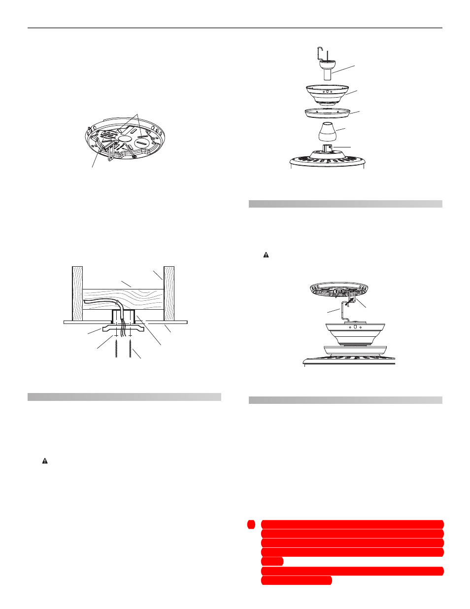
1.
Insert the downrod through the canopy, canopy trim ring and
spindle as shown in Figure 11. Feed wires from the fan through
the downrod.
2.
Screw the downrod into the fan assembly until tight. IMPOR-
TANT! Tighten downrod set screw as shown in Figure 11.
C
C
C
C
CA
A
A
A
AU
U
U
U
UT
T
T
T
TIIIIIO
O
O
O
ON: T
N: T
N: T
N: T
N: Th
h
h
h
he d
e d
e d
e d
e do
o
o
o
ow
w
w
w
wnr
nr
nr
nr
nro
o
o
o
od h
d h
d h
d h
d ha
aa
aas a s
s a s
s a s
s a s
s a sp
p
p
p
pe
ee
eeccccciiiiiaaaaal c
l c
l c
l c
l co
o
o
o
oa
aa
aatttttin
in
in
in
ing o
g o
g o
g o
g on t
n t
n t
n t
n th
h
h
h
he
ee
ee
ttttthr
hr
hr
hr
hre
ee
eeaaaaad
d
d
d
dsssss. D
. D
. D
. D
. Do n
o n
o n
o n
o no
o
o
o
ot r
t r
t r
t r
t re
ee
eem
m
m
m
mo
o
o
o
ov
vv
vve t
e t
e t
e t
e th
h
h
h
hiiiiis c
s c
s c
s c
s co
o
o
o
oa
aa
aatttttin
in
in
in
ing; t
g; t
g; t
g; t
g; th
h
h
h
he c
e c
e c
e c
e co
o
o
o
oa
aa
aatttttin
in
in
in
ing p
g p
g p
g p
g prrrrre
ee
eev
vv
vveeeeen
n
n
n
ntttttsssss
ttttth
h
h
h
he d
e d
e d
e d
e do
o
o
o
ow
w
w
w
wnr
nr
nr
nr
nro
o
o
o
od f
d f
d f
d f
d frrrrro
o
o
o
om un
m un
m un
m un
m unssssscccccrrrrre
ee
eew
w
w
w
win
in
in
in
ing
gg
gg. O
. O
. O
. O
. On
n
n
n
nccccce a
e a
e a
e a
e asssssssssse
ee
eemb
mb
mb
mb
mbllllle
ee
eed, d
d, d
d, d
d, d
d, do n
o n
o n
o n
o no
o
o
o
ottttt
rrrrre
ee
eem
m
m
m
mo
o
o
o
ov
vv
vve t
e t
e t
e t
e th
h
h
h
he d
e d
e d
e d
e do
o
o
o
ow
w
w
w
wnr
nr
nr
nr
nro
o
o
o
od.
d.
d.
d.
d.
3.
Continue to the h
h
h
h
ha
aa
aan
n
n
n
ng
gg
ggin
in
in
in
ing t
g t
g t
g t
g th
h
h
h
he f
e f
e f
e f
e fa
aa
aan
n
n
n
n section.
Figure 9 - Locating the slotted holes to use
Slots
Arrors for Orienting
on Angled Ceiling
Figure 10 - Installing the ceiling plate
Ceiling Joist
2 x 4 Brace
Ceiling Plate
Flat Washer
Ceiling
Outlet Box
3" Wood Screw
Figure 12 - Hanging the fan
Hook
Loop
Figure 11 - Assembling the downrod
Hanger Ball/
Downrod Assembly
Canopy
Canopy Trim Ring
Spindle
Set Screw