Honeywell V4055 User Manual
Page 3
V4055A,B,D,E ON-OFF FLUID POWER GAS VALVE ACTUATOR
3
60-2309—1
3
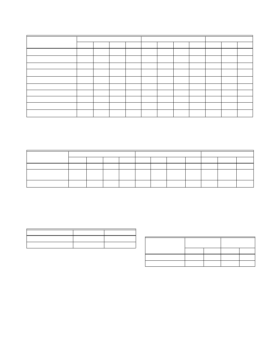
Table 3. V4055A,D Electrical Ratings.
a
50 Hz power supply.
b
60 Hz power supply.
c
230 Vac, 50 Hz power supply.
d
230 Vac, 60 Hz power supply.
Table 4. V4055B,E Electrical Ratings.
a
230 Vac, 50 Hz power supply.
b
230 Vac, 60 Hz power supply.
Auxiliary Switch and Proof-of-Closure Switch Ratings:
See Table 5.
Table 5. Auxiliary Switch and Proof-of-Closure
Switch Ratings (1/2 hp [0.37kW]
a
).
a
Maximum total connected power to both switches (if used) is
1800 VA.
Mounting Dimensions: See Fig. 1 and Table 7.
Damper Shaft: Shaft is 3/8 in. (9.5 mm) square, for use with
7616BR Damper Crank Arm (ordered separately) and with or
without damper shaft return spring.
Maximum Damper Shaft Rotation: 52 angular degrees.
Maximum Force: 2-11/16 in. (68.3 mm) radius for 7616BR
Damper Crank Arm ordered separately (see Accessories
section).
NOTE: Damper shaft drives damper crank arm in one
direction only; optional return spring is available on
damper shaft to turn damper crank arm in opposite
direction. See Table 6.
Table 6. Actuator Torque (With and
Without Return Spring).
Approvals:
Underwriters Laboratories Inc. Listed: File No. MH1639, Guide
No. YIOZ.
Factory Mutual: Listed.
Canadian Standards Association certified: General Listed file
numbers 158158 Class 3371
For U.S.A. and Canada: certified 60 Hz models only.
Swiss Re (Formerly GeGap/IRI) Acceptable.
Some V4055 Actuators are approved as Class A valves in
accordance with EN161:
When used with V5055 Valves: Pin: CE-0063AR1359.
When used with VE5000 Series Valves: Pin: CE-
0063AP3075.
Voltage and Frequency
Opening (Standard)
Opening (Fast)
Holding
Inrush
(W)
(A)
VA)
Inrush
(W)
(A)
(VA)
(W)
(A)
(VA)
100/50-60
a
—
43.0
0.91
91
—
58.0
1.30
130
10.4
0.16
16
100/50-60
b
—
33.0
0.6
67
—
43.0
0.91
91
8.4
0.14
14
120/60
3.9
50.0
0.94
115
5.4
71.0
1.33
160
9.5
0.12
14
200/50-60
a
—
68.0
0.79
158
—
88.0
1.10
220
10.6
0.09
18
200/50-60
b
—
48.0
0.52
104
—
63.0
0.72
144
9.0
0.07
14
220/50
1.6
55.5
0.55
121
3.0
76.0
0.80
176
9.0
0.06
14
240/50
—
81.5
0.79
190
—
95.0
1.00
240
9.1
0.06
14
240/60
2.6
51.0
0.45
115
4.0
71.5
0.68
160
9.2
0.06
14
220-240/50-60
c
—
—
—
—
—
70.3
0.59
136
7.2
0.07
16
220-240/50-60
d
—
—
—
—
—
58.6
0.46
106
5.9
0.06
14
Voltage and
Frequency
Opening (Standard)
Opening (Fast)
Holding
Inrush
(W)
(A)
(VA)
Inrush
(W)
(A)
(VA)
(W)
(A)
(VA)
120/60
—
60
0.94
115
—
60.0
0.94
115
9.5
0.16
19
220-240/50-60
a
—
—
—
—
—
68.9
0.58
133
6.7
0.08
18
220-240/50-60
b
—
—
—
—
—
58.2
0.46
106
5.3
0.06
14
Load
120V
240V
Full Load
9.8A
4.9A
Locked Rotor
58.8A
29.4A
V4055 Model
-40°F to +20°F
(-40°C to -7°C)
20°F to 150°F
(-7°C to +66°C)
lb
N
lb
N
With return spring
5
22.2
10
44.5
Without return spring 5
22.2
20
89.0