Front panel, Chapter 3 • remote control, Chapter three • remote control – Extron electronic 14400 User Manual
Page 10: Chapter three
Refer also to the FOX 4G Matrix 14400 User’s Manual at www.extron.com.
Front Panel
FOX 4G MATRIX 14400
CONFIG
FIBER OPTIC DIGITAL MATRIX SWITCHER
POWER SUPPLY
PRIMARY
REDUNDANT
7
8
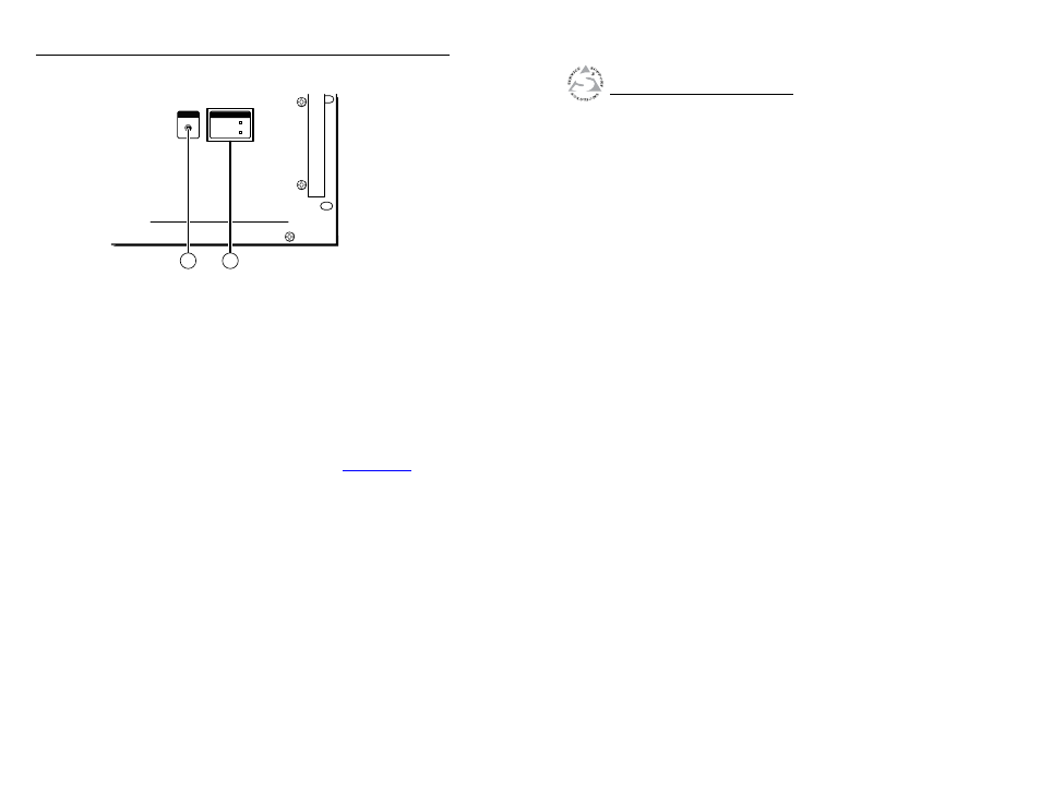
Figure 2-7 — Front panel configuration port
g
Configuration port —
If desired, connect a control system
or computer to the front panel Configuration (RS-232) port.
Use an optional 9-pin D to 2.5 mm mini jack TRS RS-232
cable, part #70-335-01.
h
Primary and Redundant Power Supply LEDs —
Green —
Indicates that the associated power supply is
operating within normal tolerances.
Red —
Indicates that the associated power supply is operating
outside the normal tolerances or has failed. See chapter 4,
“Maintenance and Modifications”, to replace the power supply.
3
Chapter Three
Remote Control
Selected SIS Commands
Installing and Starting the Control Program
Accessing the HTML Pages
FOX 4G Matrix 14400 • Installation
Installation, cont’d
2-6
FOX 4G Matrix 14400
- MTP RL 15HD A (6 pages)
- MediaLink Controllers MLC 104 Series (2 pages)
- Fiber Optic Transmitter-Receiver Pair FOX 500 Tx (3 pages)
- Priority Page Controller PPC 25 (2 pages)
- MVX 128 VGA A (4 pages)
- MVX 84 (84 pages)
- MVX 48 series (78 pages)
- DVS 204D (2 pages)
- DA2 VGA Series (3 pages)
- DVS 204 (4 pages)
- MSW 4SV rs (2 pages)
- Fiber Optic Transceivers FOXBOX 4G VGA (3 pages)
- IPI 204 AAP (2 pages)
- MediaLink Controllers MLC 206 (4 pages)
- Extron MediaLink MLS 304MA (4 pages)
- 6400s (70 pages)
- IN1404XT (82 pages)
- MMX AV Series (4 pages)
- VSW 2VGA A (2 pages)
- IP Link IPL T SF2 (6 pages)
- IN1401 (2 pages)
- VGA MATRIX SWITCHERS MVX PLUS 128 (148 pages)
- ISM 482 (105 pages)
- MTP SW6 (4 pages)
- MAV 62 Series (5 pages)
- 450 Plus (2 pages)
- Extron P/2 DA2 PLUS (1 page)
- MediaLink Controllers MLC 52 RS VC EU (4 pages)
- P/N 68-424-02 (5 pages)
- RGB 198 (2 pages)
- MTP T 15HD A D (6 pages)
- MTP DA4 (1 page)
- 726-01 (1 page)
- MMX 62 (23 pages)
- MMX VGA Series (4 pages)
- 3000B (187 pages)
- ISM 824 (4 pages)
- MMX 42 AV RCA (4 pages)
- MTP T15HD A (18 pages)
- Mini High Resolution Halogen-Free Cable MHRHF-5/150 (2 pages)
- IN1508 (2 pages)
- IPI 200 Series (100 pages)
- Extron SW 2 VGAcc (1 page)
- Matrix 12800 Series (5 pages)
- MVX Series (5 pages)