Rear panel, Ipl t s series interfaces • hardware setup, Link led — green when connected to a network – Extron electronic Extron IPL T S4 User Manual
Page 15: Com1 — 9-pin d connector for serial port 1, Com2 — 9-pin d connector for serial port 2, Com3 — 9-pin d connector for serial port 3, Com4 — 9-pin d connector for serial port 4
IPL T S Series Interfaces • Hardware Setup
2-3
a
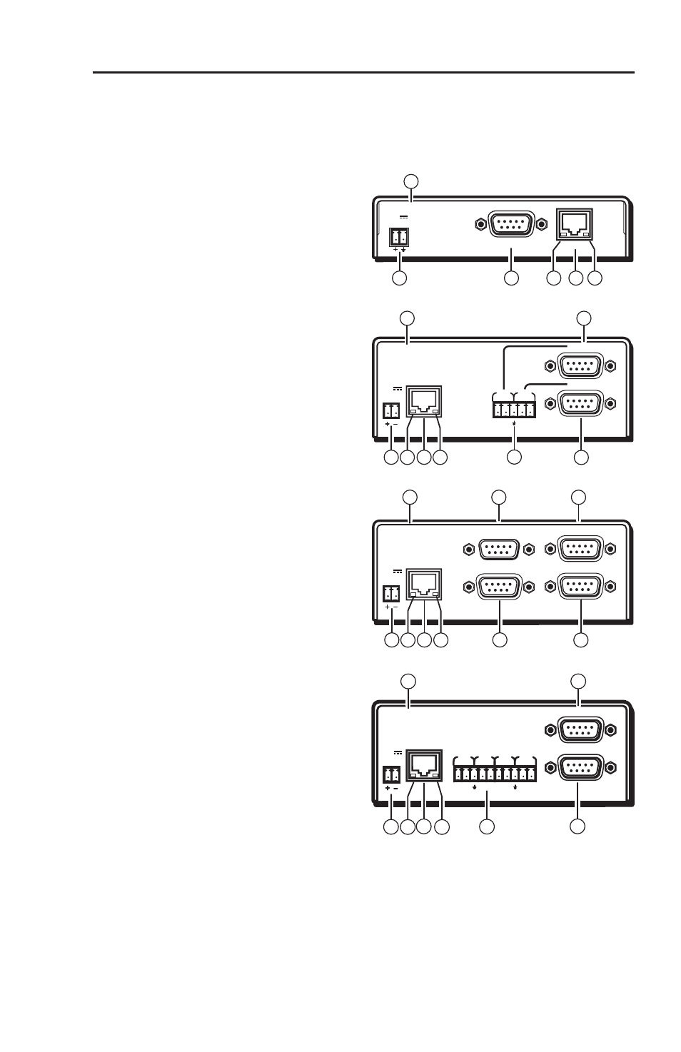
Power receptacle —
connects the supplied
12 VDC power supply
b
LAN Activity LED —
yellow
LED blinks when sending
and receiving data
c
LAN receptacle —
RJ-45
receptacle for network
connection
d
Link LED —
green when
connected to a network
e
Captive screw connectors
—
3.5 mm, 5-pole, captive
screw connectors for serial
port connections
f
COM1 —
9-pin D connector
for serial port 1
g
COM2 —
9-pin D connector
for serial port 2
h
COM3 —
9-pin D connector
for serial port 3
i
COM4 —
9-pin D connector
for serial port 4
j
UID # —
The unique User
ID Number (MAC address)
of the unit
(ex: 00-05-A6-00-00-01)
Rear Panel
The rear panel has connectors for power, control, signal input, and signal
output, and indicators as described below.
12V
0.5 A
LAN
COM1
00-05-A6-00-00-01
10
IPL T S1
1
6
2
3
4
COM1
LAN
00-05-A6-00-00-02
POWER
12V
.5A MAX
COM1
TX RX
TX RX
COM2
COM2
10
6
1
7
5
3
2
4
IPL T S2
COM3
LAN
00-05-A6-00-00-04
POWER
12V
.5A MAX
COM4
COM1
COM2
1
7
3
2
4
9
10
6
8
IPL T S4
COM1
LAN
POWER
12V
.5A MAX
COM5
TX RX
TX RX
COM6
COM3
TX RX
TX RX
COM4
COM2
00-05-A6-00-00-06
6
10
7
5
1 2
4
3
IPL T S6