Introduction – Emerson 1F97-391 User Manual
Page 5
3
FAN AUTO
HRS
CHECK BATTERY
F
AM
MON
FAN AUTO
HEAT
HEAT
HRS
CHECK BATTERY
F
AM
MON
WED THU FRI SAT SUN
TUE
WED THU FRI SAT SUN
TUE
18
18
19
20
21
22
25
23
24
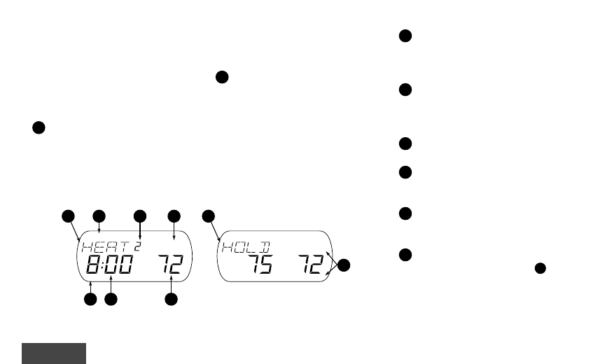
Figure 1. The Display
LAR
LAR
LAR
LAR
LARGE LIGHTED (L
GE LIGHTED (L
GE LIGHTED (L
GE LIGHTED (L
GE LIGHTED (LCD) DISPLA
CD) DISPLA
CD) DISPLA
CD) DISPLA
CD) DISPLAY
Y
Y
Y
Y
The thermostat display alternately shows
the current time and the current tempera-
ture on the left side. The display also
shows the temperature you have pro-
grammed or set on the right side of your
screen.
18
Displays system mode (
HEA
HEA
HEA
HEA
HEAT
T
T
T
T, OFF
OFF
OFF
OFF
OFF,
COOL
COOL
COOL
COOL
COOL, A
A
A
A
AUT
UT
UT
UT
UTO
O
O
O
O, HOLD
HOLD
HOLD
HOLD
HOLD, V
V
V
V
VA
A
A
A
ACA
CA
CA
CA
CA or
HUMD
HUMD
HUMD
HUMD
HUMD). During programming displays the
time period (
MOR,
MOR,
MOR,
MOR,
MOR, D
D
D
D
DA
A
A
A
AY
Y
Y
Y
Y,,,,, EVE,
EVE,
EVE,
EVE,
EVE, NHT
NHT
NHT
NHT
NHT)
being programmed. In the configuration
menu, the menu item name is shown, one
word at a time (
PR
PR
PR
PR
PRGM
GM
GM
GM
GM MODE
MODE
MODE
MODE
MODE, EMR
EMR
EMR
EMR
EMR,
COOL
COOL
COOL
COOL
COOL F
F
F
F
FAN
AN
AN
AN
AN DELA
DELA
DELA
DELA
DELA OFF
OFF
OFF
OFF
OFF, etc.).
19
CHECK B
CHECK B
CHECK B
CHECK B
CHECK BA
A
A
A
ATTER
TTER
TTER
TTER
TTERY
Y
Y
Y
Y appears when the
“AA” alkaline batteries are weak and
should be replaced.
B
B
B
B
BA
A
A
A
ATTER
TTER
TTER
TTER
TTERY
Y
Y
Y
Y appears
when the thermostat is running on battery
power only.
CHECK ST
CHECK ST
CHECK ST
CHECK ST
CHECK STA
A
A
A
AT
T
T
T
T appears when
the thermostat detects certain problems
within itself.
CHECK SY
CHECK SY
CHECK SY
CHECK SY
CHECK SYSTEM
STEM
STEM
STEM
STEM appears
when the thermostat detects certain
problems in the heating or humidity
system.
20
Indicates the length of time remaining
in a temporary hold condition. Also
indicates the length of time remaining in
VACATION mode.
21
Displays
F
F
F
F
FAN ON
AN ON
AN ON
AN ON
AN ON when the fan is
operating continuously. Displays
F
F
F
F
FAN
AN
AN
AN
AN
A
A
A
A
AUT
UT
UT
UT
UTO
O
O
O
O when the fan cycles with the
heating or cooling system.
22
Displays the setpoint temperature. In
HUMD mode, shows humidity setpoint.
23
Alternately displays room temperature
and time of day. In HUMD mode, shows
actual humidity.
24
Shows the current day of the week.
When programming, shows the day(s)
being programmed.
25
The word
HEA
HEA
HEA
HEA
HEAT
T
T
T
T or COOL
COOL
COOL
COOL
COOL will appear
above or below the setpoint if area
18
is
needed to display other information.
Introduction