Menu – EverFocus EDSR100H User Manual
Page 28
MENU
Note:
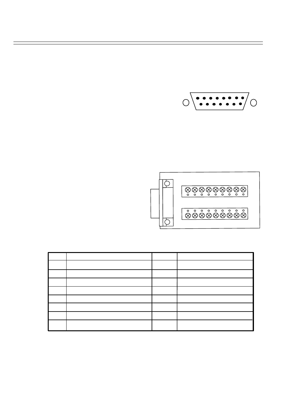
Alarm Connectors (DB-15)
PIN # NAME
PIN #
NAME
1
GND
9
GPOUT
2
ALARM
10
DISK_FULL
3
RECIN
11
VD_LOSS
4
NC1
12
VCR_SW
5
NC2
13
ALM_NC
6
ALMRST
14
ALM_NO
7
GPIN
15
ALM_COM
8
GND
The alarm connector, figure 1, is used to provide one
sensor alarm input for each camera input.
For easy operation, an alarm extension board,
figure 2, is provided to connect to the alarm
connector.
Each alarm input requires two wires, one wire
connects to the desired alarm input pin, the
second wire connects to the multiplexer
ground. The alarm signal assignment is shown
at the following table, table 1.
9
15
1
8