Advanced installation and setup instructions, Installing temperature sensor(s), Installing the rpm sensor – Eagle Tree Systems Seagull Glide User Manual
Page 7
Copyright © 2003-2005 Eagle Tree Systems, LLC
Page 7
Advanced Installation and Setup Instructions
This section describes more advanced setup and configuration. A computer is required for
this section, and some features listed require optional accessories.
Installing Temperature Sensor(s)
If you purchased optional Temperature Sensors, you will be able to monitor up to two
temperatures with your system. Plug the Futaba style connector from the sensor into the
recorder as shown in Figure 1.
Note: the Temperature Sensor lead can be easily extended with a standard servo extension
cable.
Installing the RPM Sensor
If you purchased the optional RPM Sensor kit, you will be able to measure the RPM of your
motor. Installing the RPM sensor and magnets is the most challenging part of installation,
but is relatively easy once a good mounting location is determined. Refer to our website’s
Flight support page at
http://www.eagletreesystems.com
for pictures of example
installations.
First find a suitable location on your engine’s motor to attach either one or two small magnets and RPM sensor. Typically, the prop
washer or prop hub are ideal locations. This will of course vary with make and model of plane. Make sure the magnets are mounted
on some structure that doesn’t “flop around,” as the magnets could hit the sensor in this case. The RPM sensor must be mounted so
that it does not move around, and is within 1-2 mm of the two magnets as they spin. On typical plane installations, there’s usually a
place where the back of the sensor can be glued to a flat surface under or over the hub which has the magnets mounted. The
Recorder kit includes four magnets. That provides you with up to 3 spares.
Installing Magnets
Once you have determined where to install the magnets, decide whether you will drill a hole so that the magnets will mount flush with
the surface, or if you will just glue the magnets to the surface. Though somewhat more difficult and permanent, mounting the
magnet flush with the surface is the best long term approach, since the mounting will be much more rugged, and the risk of imbalance
due to not mounting the magnets exactly 180 degrees apart is reduced. In fact, if the magnet is mounted flush in another metal
material, it is quite possible that no shaft imbalance will occur if you only mount one of the magnets total.
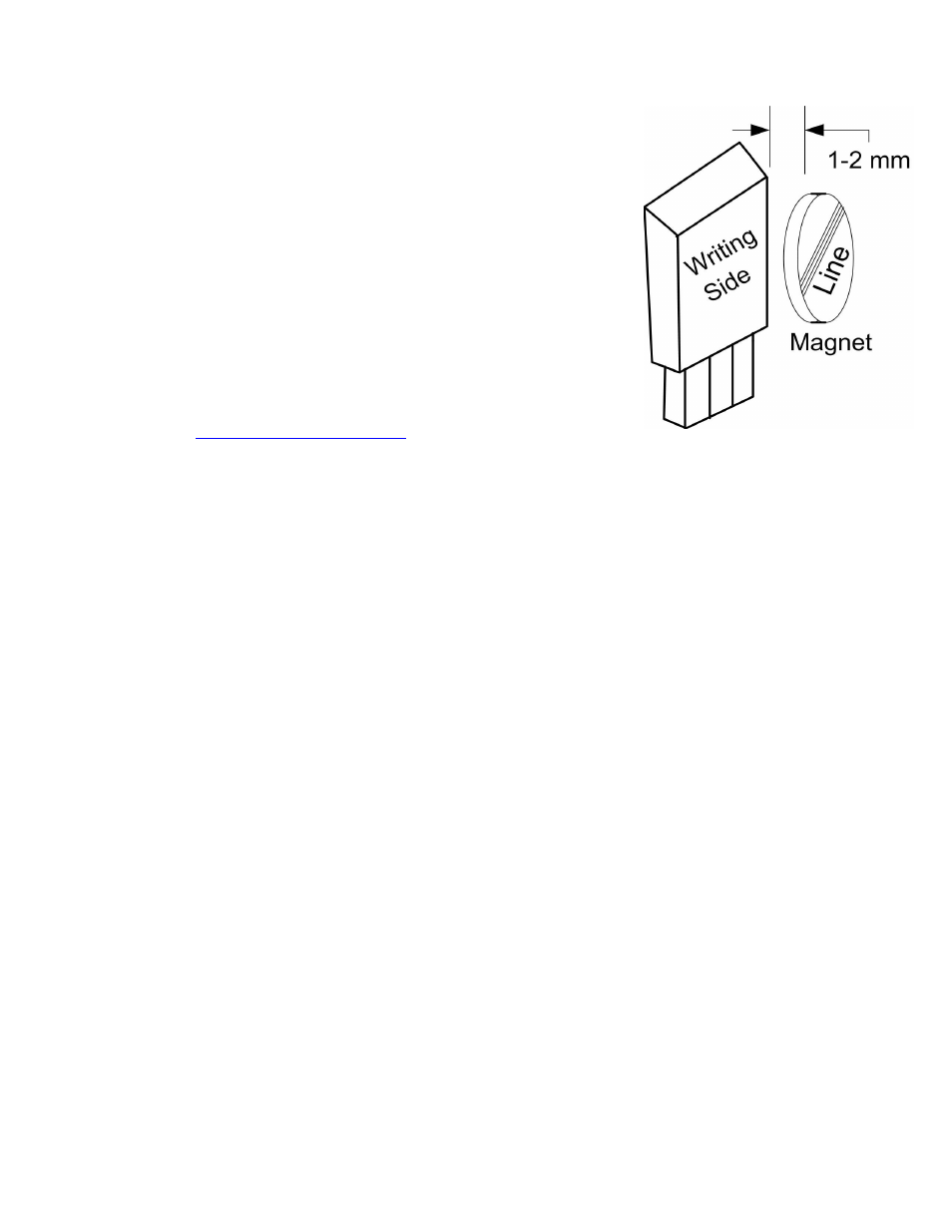
To flush mount the magnets, drill a hole just slightly larger than the diameter of the magnet size you choose, and of the same depth as
that magnet. If you decide to surface mount the magnets, thoroughly clean this area and lightly scuff it to improve adhesion. Glue
the magnets with the side marked with a red line facing inward (hidden), using epoxy, or other strong, suitable glue. It’s important
that the red line on the magnets faces away from the sensor once the sensor is installed. The magnets should be glued 180 degrees
apart to keep the shaft in balance.
WARNING: make sure that the magnets are glued sufficiently so that they will not detach and create a hazard, and always
wear safety glasses when your engine is running! It is also a good idea to put a piece of heatshrink tubing or electrical tape
around the magnets, to further secure them.
Using Existing Magnets
Note: if your engine already has magnets mounted for some other purpose, there’s a good chance you can use them. Take one of the
magnets included with your recorder, and put that magnet up against the previously mounted magnet. If the red line of the Recorder
magnet faces down so that the sensor can be mounted facing the side of the magnet with no red line, mount the sensor with the printed
side toward the magnet. If the side of the magnet with the red line is visible when on top of the previous magnet, the polarity is
reversed. This should work correctly if you install our sensor backwards (printed side of sensor away from magnets), though we have
not tried it.
We are often asked whether existing magnets on spark ignition engines can be used. The answer is “yes” in most cases, if you can
install the sensor near enough to rotating magnets. We have found that these engines typically have 3 magnets, with 2 magnets
mounted with one polarity, and the other one with another polarity. The easiest way to use these magnets is to install the sensor with
the printed side facing the magnets (as described below) then run the motor and see what RPMs are recorded after setting up the gear
ratio. If the RPM looks like it is only half of the correct value, double the gear ratio value you entered, to compensate for only one