Cm series getting started, Rack mounting, Connections – Lab.gruppen CM41 Commercial Mixer User Manual
Page 7: Input routing, Priority and vox, Remote
12
CM Series
Quick Start Guide
13
CM Series Getting Started
Rack Mounting
The CM series amplifiers come with rubber feet that
enable the amps to be placed on a clear surface
without an additional installation. However, optional
rack mounting hardware is also supplied, allowing
several models to be housed and protected inside a
19" rack enclosure. Follow these steps to attach the
mounting hardware.
A pair of CM41 units can be mounted side-by-side to
occupy a single rack space. Attach the coupling plate
to the underside of 2 CMA1201 units using the
included screws. Alternatively, a single CMA1201 unit
can be installed in the rack using the long
angle bracket..
Attach the front angle brackets to either side of a
CM82 unit, or a pair of CM41 units that have
been coupled..
If your rack has rear rails, attach the rear flat brackets
with the included screws.
Mount the CM unit(s) into the rack by attaching
4 rack screws through the front angle brackets and
rack rails.
Hold one of the rear angle brackets up to the rear
rack rails so that it lines up next to the rear flat
bracket. Do not attach it to the rear rails yet.
Insert the included shoulder screw through the slot
in the rear flat bracket and into one of the threaded
holes in the rear angle bracket. The screw should
allow the rear angle bracket to slide forward and
back within the flat bracket’s slot.
Repeat the process for the other rear angle bracket.
Mount the rear angle brackets to the rear rack rails
using 4 standard rack screws.
Tighten the shoulder screw if necessary.
Standard rack screw: M4 x 8 mm.
Connections
For balanced or microphone input connections,
use a 3-pole cable (hot, cold, ground) wired to a
Euroblock connector. Alternatively, RCA cables can
be connected for unbalanced stereo sources, but
the RCA and Euroblock inputs should not be used
together on the same input. Note that stereo signals
will be summed to mono.
Output signals use the same Euroblock connector as
the inputs.
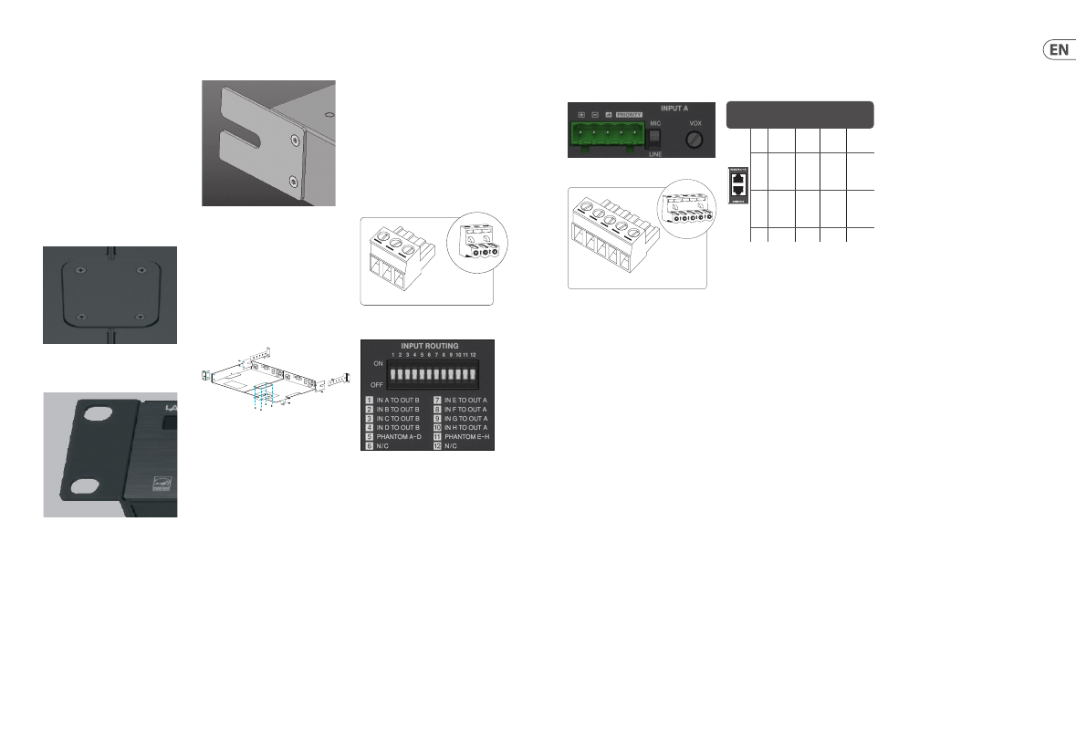
Input Routing
For CM82 units, the routing of inputs to outputs can
be controlled with the input routing dipswitches.
By default (switches down), Inputs A-D are routed
to Output A and Inputs E-H are routed to Output B.
However, for sources that should be sent to both
outputs, the corresponding dipswitch can be
engaged to route an input to the other output
channel as well. This is useful, for example, to send
background music or paging messages to both
zones/sections of a building but maintain other
sources local to each zone.
Phantom power (48 V) can also be supplied to
channels A-D and E-H independently by engaging
the corresponding dipswitch.
3-Pin Euroblock Connector - Input / Output
1
2
3
1. hot (+)
2. cold (-)
3. ground/shield
Priority and Vox
Inputs A and B (Input A only on CM41) have the
ability to mute all other channels when the Priority
function is activated. Activation is achieved by
shorting the 2 Priority pins with a closure switch,
often found on paging mics. Alternatively, the
activation can also be done by the signal on the
prioritized input exceeding a set level(threshold).
Turning the VOX knob counterclockwise sets the
input level required to engage ducking. Set it so that
speaking clearly into the mic exceeds this threshold,
but ambient noise is ignored. Turning the VOX knob
fully clockwise (OFF) disables this feature. For CM82,
the ducking affects all other sources that are
routed to the same output as the prioritized input.
For example, if Input A is routed also to Output B,
Input A will have priority over all other inputs.
Input E, however, cannot have priority over the
Output A inputs.
Remote
RJ45 receptacle to connect an optional remote
volume control per channel. Use a standard cable to
connect the CRC-V accessory, or connect a custom
potentiometer with the pinout information.
Cable length above 305 m (1000 ft) is not
recommended.
5-Pin Euroblock Connector - Remote
1
2
3
4
5
1. priority 1
2. priority 2
3. ground/shield
4. cold (-)
5. hot (+)
RJ-45
Pin
Color
(T568B)
Remote
(1 channel
products )
Remote
A+B
Remote B
1
White/
Orange
VCC
10 V
VCC
10 V
VCC
10 V
2
Orange Volume
Control
Volume
Control
Channel
A
Volume
Control
Channel
B
3
White/
Green
N/A
Volume
Control
Channel
B
N/A
8
Brown Ground Ground Ground