Cv-pt-head manual – Marshall Electronics Motorized Micro PT Pan/Tilt Head for Select CV Series Cameras User Manual
Page 3
CV-PT-HEAD Manual
www.marshall-usa.com
3
4
The
CV-PT-HEAD
contains 10 gears. Some controllers can select any gear, but others can only
select a fewer number of gears. The movement is fully proportional to the joystick displacement in
all gears.
If the ‘turbo’ button is enabled on the controller this will set the speed to the fastest gear triggered
by holding down the button.
The
CV-PT-HEAD
has the capacity to store up to 64 pre-set positions although some controllers
can only access 4 positions. When first powering the unit on you will need to manually set a ‘Home’
position or storing the positions you need. You can set a ‘Home’ position by using a known picture
position from the camera or by driving it to the ends of the pan and tilt travel. Doing this will enable
it to re-call previously stored positions.
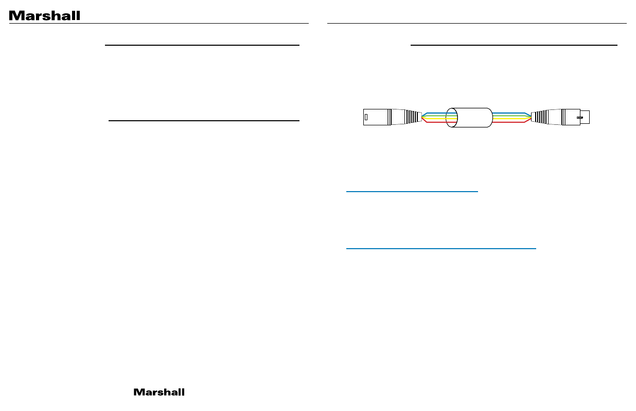
The
CV-PT-HEAD
is supplied with a short cable to connect it to a controller. This cable can be
simply extended following the wiring diagram below.
When power is connected the blue LED on the side will flash 3 times whilst the
CV-PT-HEAD
is
booting up. After this sequence, the LED will indicate 3 states.
Permanently ON
= Power applied; data received but not being addressed.
Very Fast Flashing
= Being addressed and should respond to commands.
Flashing Very Slowly
= Power but no data.
4 Pin input plug – FGG.0B.304.CLAD52Z
Pin 1 = GND (Blue)
Pin 2 = RS485 data A (Green)
Pin 3 = RS485 data B (Yellow)
Pin 4 = Power 12 – 35v (Red)
7 Pin plug for camera power & data - FGG.0B.307.CLAD52Z
Pin 1 = GND (Blue)
Pin 2 = RS422/485 data A TO camera (Green) Also semi-duplex return data.
Pin 3 = RS422/485 data B TO camera (Yellow) also semi-duplex return data.
Pin 4 = Power 12v camera power (Red)
Pin 5 = future use
Pin 6 = future use
Pin 7 = future use
2. Joystick Control
3. Pre-set Positions
4. Connections
XLR4 (NC4MXX)
1 Blue (GND)
2 Green
3 Yellow
4 Red (+12v)
XLR4 (NC4FXX)
1 Blue (GND)
2 Green
3 Yellow
4 Red (+12v)
1 Blue (GND)
2 Green
3 Yellow
4 Red (+12v)
XLR4 (NC4MXX)
1 Blue (GND)
2 Green
3 Yellow
4 Red (+12v)
XLR4 (NC4FXX)
1 Blue (GND)
2 Green
3 Yellow
4 Red (+12v)
XLR4 (NC4MXX)
1 Blue (GND)
2 Green
3 Yellow
4 Red (+12v)
XLR4 (NC4FXX)