Rear panel, Sockets and switches – SPL Track One Channel Strip User Manual
Page 10
10
Track One
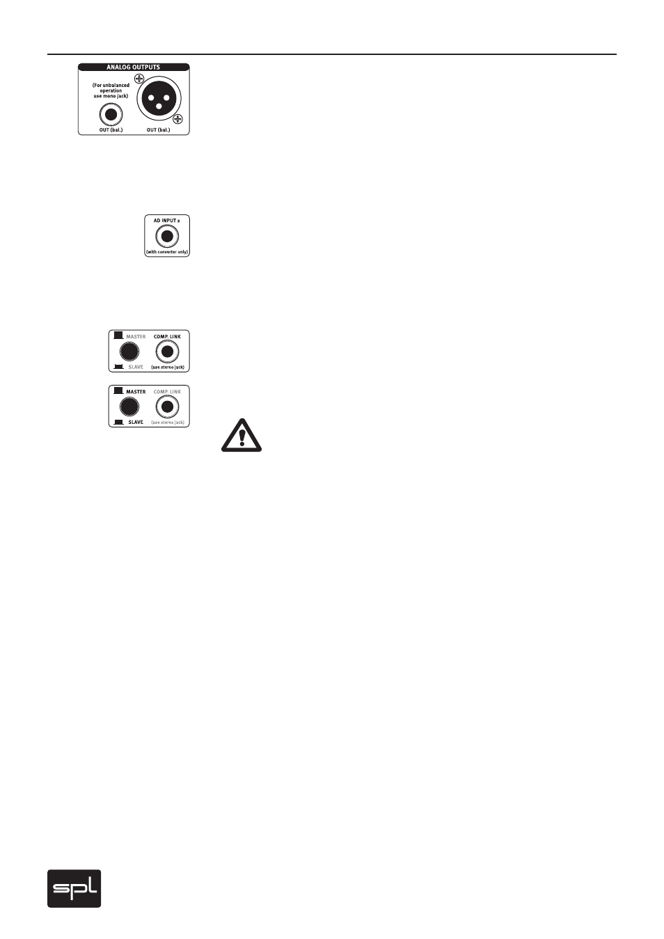
ANALOG OUTPUTS
The ANALOG OUTPUTS deliver balanced output signals. An output trans former can be
equipped optionally (see page 29).
Since both connectors are working in parallel, unbalancing one connector also unbalances
the other one. If for example a mono jack connector is plugged into to the jack socket, the
XLR socket is operating unbalanced as well. Depending on the impedances of the connected
devices, a parallel use of both outputs can reduce the signal level. Therefore, we recommend
to use either the XLR or the 1/4" TRS output socket.
A/D INPUT 2
The Track One is a mono channel strip, but the optional A/D converter card 2376 is a dual-
channel device. Therefore a second (external) signal can be converted with the converter
card, if it is connected to the AD INPUT 2. If no signal is connected to the A/D INPUT 2, the
output signal of the Track One is routed to both converter channels. The maximum input level
for the converter is +12dBu (=0 dBFS).
COMP. LINK, MASTER/SLAVE
The COMP. LINK (compressor link) feature allows to operate two Track One compressors with
one control signal to ensure coherent stereo results.
The MASTER/SLAVE switch determines which unit operates as master and which unit is being
controlled as slave.
CAUTION – PLEASE NOTE: Never switch two connected units to MASTER! Both
units would try to control each other - in worst cases, damaging the units can not
be excluded.
Therefore, always follow this procedure when activating COMP. LINK:
1. Determine the master device (switch not pressed).
2. Determine the slave device (switch engaged).
3. NOW connect both COMP. LINK sockets with a stereo jack wiring. Always determining
the device status before connecting the COMP. LINK sockets excludes a mutual control
activity.
In COMP. LINK mode the master device controls the COMPRESSION, MAKE UP and LIMIT
controls of both compressors. The respective controls on the slave unit are deactivated. The
COMP. ON switch is not slaved. The GAIN REDUCTION metering of the master unit now is the
master display for both units.
If the two units are to be used separately again, the wiring must be disconnected and the
slave unit must be set to master again.
Rear Panel
Sockets and switches