Installation, Functional test, Continued) – Emerson ASCO 7000 User Manual
Page 4: Harnesses, Engine starting contacts, Auxiliary circuits, 1 – manual operation test
INSTALLATION
(continued)
1---2
Harnesses
The transfer switch is connected to the left side of the
controller by a plug-in harness (two plugs).
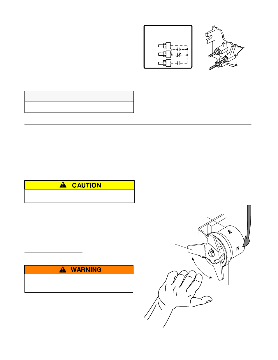
Engine Starting Contacts
The engine control contact connections (if used) are
located on the transfer switch. Connect signal wires to
appropriate terminals as specified in Table A and shown
in Figure 1-2.
Table A. Engine Start Connections
When normal
source fails
Terminals on
transfer switch
contact closes
TB14 and TB15
contact opens
TB14 and TB16
TB 14
TB 15
TB 16
ENGINE STARTING CONTACTS
( SHOWN DE–ENERGIZED )
TOP
STUD
MIDDLE
STUD
BOTTOM
STUD
14
15
16
TS
NR
NR
Figure 1-2. Engine starting contact label
and location on left side of transfer switch.
Auxiliary Circuits
Connect auxiliary circuit wires to appropriate terminals on
the transfer switch. Note the control features that are
furnished on this switch. Make the necessary auxiliary
connections by referring to the Wiring Diagram.
Functional Test
The Functional Test consists of three checks:
S
1 — Manual Operation Test, on this page
S
2 — Voltage Checks, page 1–3
S
3 — Electrical Operation, page 1–4
Do these checks in the order presented
to avoid damaging the ATS.
Read all instructions on the Wiring Diagram and labels
affixed to the automatic transfer switch. Note the
control features that are provided and review their
operation before proceeding.
1 – Manual Operation Test
A maintenance handle is provided on the Transfer Switch
for maintenance purposes only. Manual operation of the
transfer switch should be checked before it is energized
(operated electrically).
Do not manually operate the transfer switch
until both power sources are disconnected:
open both circuit breakers.
1. After deenergizing both power sources, open the
enclosure door. Locate and the maintenance handle
on the left side of the transfer switch. See Figure 1–3.
2. Grasp the attached maintenance handle and turn it
with thumb and fingers as shown to manually operate
it. The maintenance handle turns the opposite
direction of the weight. Turn it up or down as shown
to manually operate the transfer switch. It should
operate smoothly without any binding. If it does not,
check for shipping damage or construction debris.
3. Return the transfer switch to the Normal position.
Note: If Normal and Emergency connections are
reversed this operation is also reversed.
Now continue to 2 – Voltage Checks on next page.
maintenance
handle
With ALL POWER OFF grasp
maintenance handle and turn it
quickly with your thumb and fingers.
weight marked N (normal)
and E (emergency)
floating
weight
weight
Position of the transfer switch is indicated here
Figure 1–3. Maintenance handle and positions.