3 typical main circuit wiring examples – Yaskawa AC Servo Drives DC Power Input Sigma-5 Series User Manual
Page 38
3.3 Main Circuit Wiring
3-9
3
Wiring and Connection
3.3.3
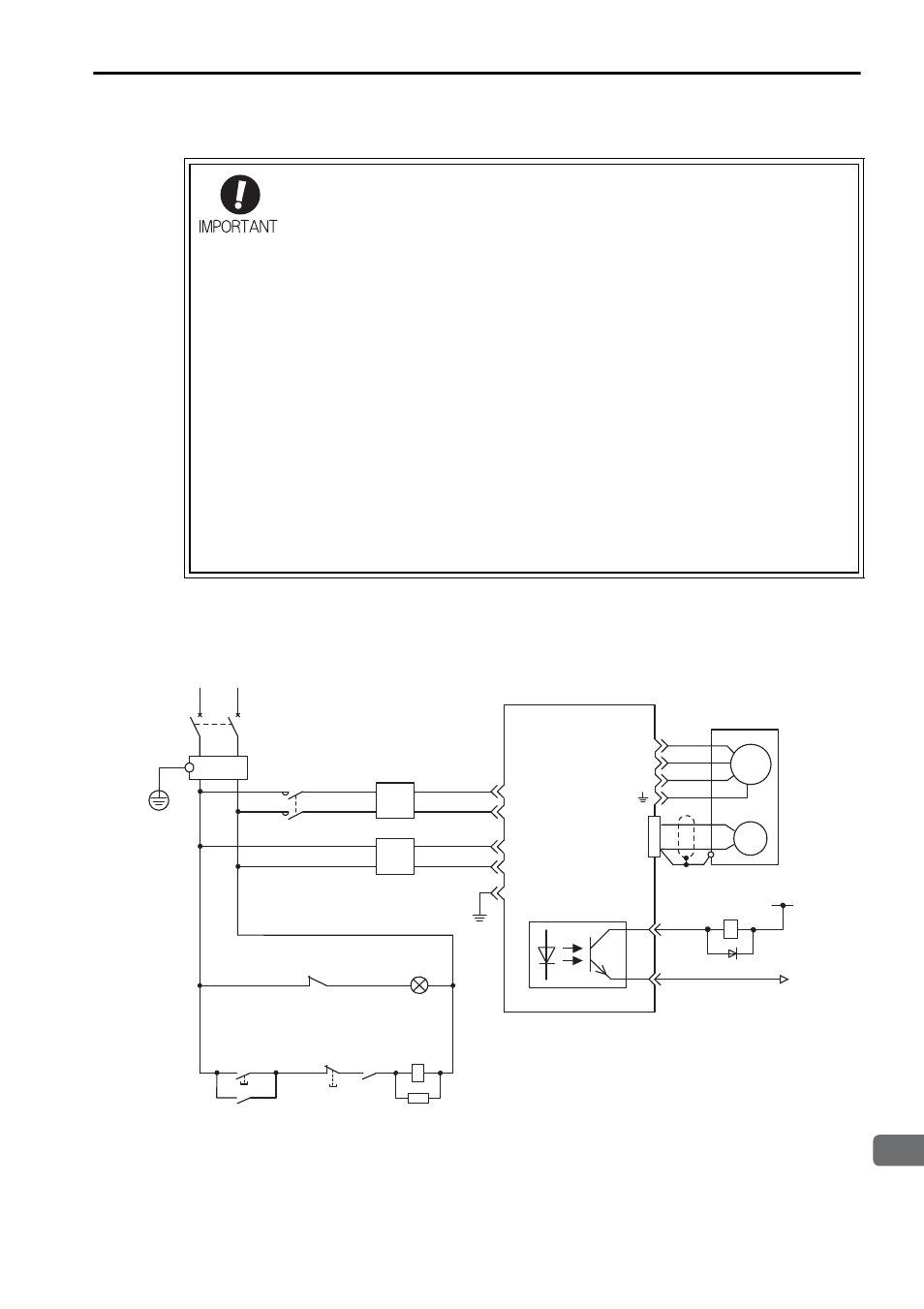
Typical Main Circuit Wiring Examples
The following wiring examples show the DC Power Input
Σ
-V Series SGDV SER-
VOPACK (Analog voltage reference model).
SGDV-
ES1A (
= 1R7, 2R9)
• Use a molded-case circuit breaker (1QF) or fuse to protect the
servo system.
Always use a molded-case circuit breaker (1QF) or fuse to pro-
tect the servo system from accidents involving different power
system voltages or other accidents.
• Install a ground fault detector.
The SERVOPACK does not have a built-in protective circuit for
grounding.
To configure a safer system, install a ground fault detector
against overloads and short-circuiting, or install a ground fault
detector combined with a molded-case circuit breaker.
• Do not frequently turn power ON and OFF.
• Frequently turning power ON and OFF causes elements
inside the SERVOPACK to deteriorate. Do not use the servo
drive with an application that requires frequently turning power
ON and OFF.
• After the actual operation starts, the allowable interval for turn-
ing power ON and OFF is one hour or longer.
L1
ENC
SGDV SERVOPACK
U
V
W
M
0 V
1Ry
8
11
1D
1KM
Insulated AC/DC
converter for main
circuit power supply
L2
CN1
1QF
R
T
+24 V
(For servo
alarm display)
1Ry
1PL
1KM
1SA
Servo
power
supply
ON
Servo
power
supply
OFF
1KM
1Ry
1QF
1FLT
1KM
: Molded-case circuit breaker
: Noise filter
: Magnetic contactor
(for main power supply)
1Ry
1PL
1SA
1D
: Relay
: Indicator lamp
: Surge absorber
: Flywheel diode
C1
C2
FG
ALM
COM_SG
1FLT
CN4
CN3
Insulated AC/DC
converter for control
circuit power supply