Initial installation – Enviro C-11288 User Manual
Page 14
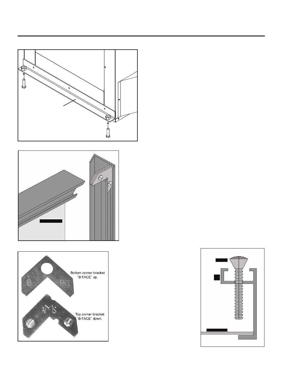
a) Attach one side trim to the top trim using a corner bracket
(see Figure 16) to secure pieces together. There are two
(2) main pieces to each corner bracket (see Figure 17).
When installing the corner pieces into the trim the “B
FACE” sides must face each other and the screw heads
are to face out. With the bracket in place and the top and
a side trim snug together use a flat head screwdriver to
turn the two (2) screws in the bracket in to tighten it into
the trim.
b) Slide the two (2) attached trim pieces onto the surround
panel.
c) Attach the other side trim piece to the top trim using the
same method used in Step a.
6. Install the leveling legs. Thread the two (2) 5”
(13 cm) bolts and locknut up into the captive nuts
at each end of the leveling leg bracket (refer to
Figure 15).
7. Place the unit part way into the fireplace.
Connect the fireplace insert’s flexible gas line to
the household gas supply, using locally approved
methods. Place the electric cable so it can be
connected to the power supply.
8. As you push the unit into its final position in the
fireplace, reinstall the vent collar plate to the
stove by sliding it along the draft hood and secure
with the screw. Adjust the leveling legs to ensure
the unit is level.
8. The trim set for your surround panel, must be
installed before installing the surround panel onto
the unit.
Figure 15: Installation of Leveling Legs.
Leveling legs bracket
Initial Installation
d) Place the second side of the
trim on the surround panel in
the same manner use on the
first side and secure in the same
manner.
e) On the side trims there are holes
2” (50 mm) from either end.
Using a Phillips screwdriver to
place a #8 screw 11⁄4” long in
each hole and tighten (refer to
Figure 18). This will keep the
trim tight against the surround.
NOTE: The notch at the bottom of
the left trim is so the power cord
can be run to the outside of the
panel.
14
Figure 18: Screw to hold the
trim against the surround.
Figure 16: Corner brackets for trim.
Figure 17: Two pieces of corner bracket.