Optional blower installation instructions – Empire Comfort Systems RH-65C-1 User Manual
Page 16
Page 16
12822-2-0903
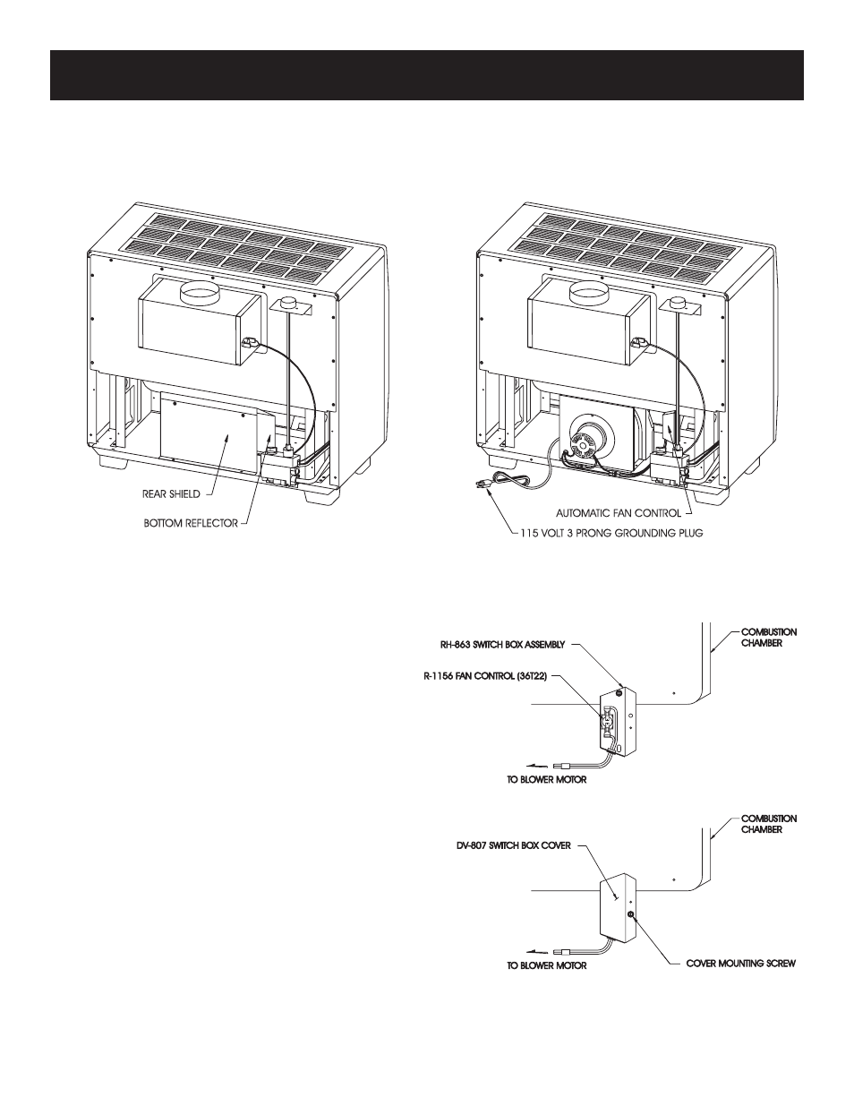
Figure 4
Installing Optional Blower
1. Remove rear shield (2 screws) and bottom reflector (4
screws). (See Figure 1)
2. Align blower cushion with bottom assembly air discharge
opening. Foil face side of blower cushion should be placed
upward.
3. Align blower housing with blower cushion and use two, #10
x 1/2" (13mm )hex-head screws to attach blower housing to
bottom assembly. (See Figure 2)
4. Save bottom reflector and rear shield (removed in Step 1) in
the event the blower housing is removed from room heater.
Attention! Bottom reflector and rear shield must be
attached to bottom assembly whenever the blower hous-
ing is removed from the room heater and the room heater
is in operation.
5. Remove switch box cover from the switch box by removing
the #8 x 1/4" (6mm) hex-head screw.
6. There are two screw holes on the lower back of the combus-
tion chamber. Use only the left screw hole for mounting.
7. With the switch box perpendicular to the combustion cham-
ber, align the round clearance hole on the switch box with the
left screw hole on the combustion chamber. (See Figure 3)
8. Attach switch box to the combustion chamber using the #10
x 1/2" (13mm) hex- head screw provided.
9. Attach switch box cover to the switch box by using the #8 x
1/4" (6mm) hex- head screw. (See Figure 4)
Figure 1
Figure 2
Figure 3
FRB-3 For Vented Room Heaters
Models
RH-50-(1, 2, 4, 5, 6)
RH-50C-1
RH-65-(1, 2, 4, 5, 6)
RH-65C-1
OPTIONAL BLOWER INSTALLATION INSTRUCTIONS