Trouble shooting and maintenance – Elkay ERO28C*B User Manual
Page 4
97114C (Rev. F - 01/01)
ERO28C*B ER028RAC*B
PAGE 4
FOR PARTS, CONTACT YOUR LOCAL DISTRIBUTOR OR CALL 1.800.323.0620
ELKAY MANUFACTURING COMPANY 2222 CAMDEN COURT OAK BROOK, IL 60523 630.574.8484
PART NO.
ITEM NO.
PARTS LIST
1
2
3
4
5
6
7
8
9
10
11
12
13
14
15
16
17
18
19
20
21
22
23
24
25
26
27
28
29
30
31
32
33
34
35
36
37
38
39
40
41
42
43
44
45
DESCRIPTION
TROUBLE SHOOTING AND MAINTENANCE
Orifice Assy
Housing Assy
Pedestal
Bubbler Locknut
Drain
Retaining Nut
Regulator Holder
Regulator
Fountain Body-Short
Fountain Body-Long
Bottom Cover Plate-Short
Bottom Cover Plate-Long
Upper Panel
Lower Panel
Screw #8-32 X .38" TH
Strainer
Hex Nut
Speed Nut
Union-3/8 X 1/4
Regulator Mounting Bracket-Long Ftn
Solenoid Mounting Bracket
Regulator Mounting Bracket-Short Ftn
Sensor Support Mounting Bracket
Solenoid Valve Assy
Power Cord
Sensor Assy
Washer - Star #10
Screw - #8-18 X .37 HHSM
Nut - Regulator
Hex Nut #10-32
Push Button
Push Button Sleeve
Strain Relief
Spacer - 1/2 X .44
Set Screw #6-32 X .31"
Screw - #10-24 X .38 PHTC
Screw - 1/4-20 X .38 HHTC
Elbow - 1/4 X 1/4
Tee - 3/8
Union - 3/8 Stem X 1/4 Tube
Fitting - 1/4 NPTF X 1/4 O.D.
Screw - #10-24 X .62 HHMS
Screw- 5/16-18 X .75
Hex Nut - 5/16-18
Poly Tubing 48" (Cut To Length)
A54874
50934C
50168C
70012C
LK464
15005C
50986C
61313C
55000604
27623C
55000661
55000665
26839C
26833C
110711942550
55996C
40045C
70055C
70745C
22525C
22526C
27057C
27240C
31272C
31376C
31384C
34783003
38417001
56082C
70016C
45662C
45663C
50203C
51409C
70022C
70208C
70256C
70817C
70852C
75491C
75507C
111008343890
111577243890
111577343890
56092C
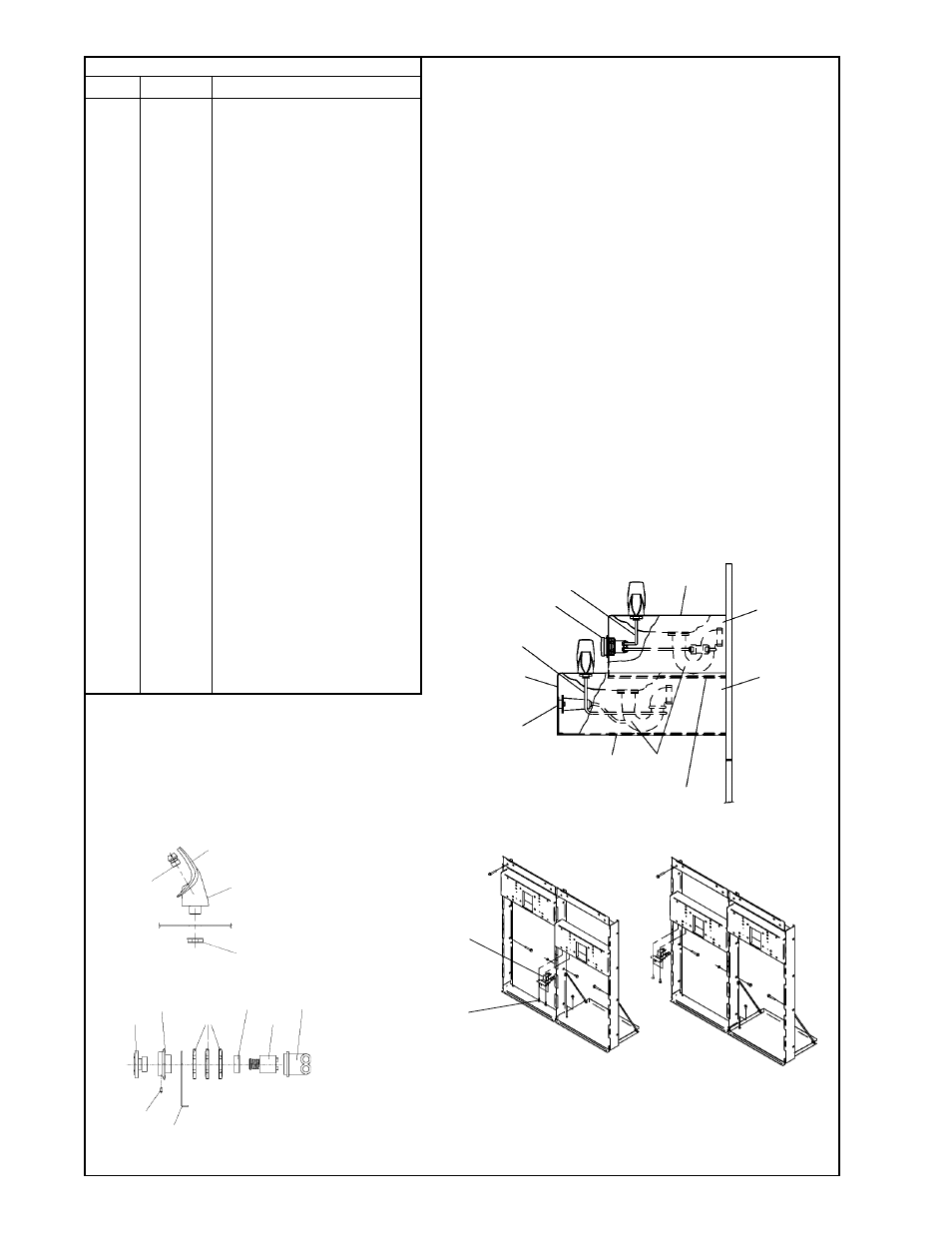
FIG. 7
FIG. 6
SEE FIG. 8
5
11, 15, 18
9
SEE FIG. 5
10
12, 15, 18
1. Orifice Assy: Minerals deposits on orifice can cause water flow to spurt or not
regulate. Mineral deposits may be removed from the orifice with a small round
file not over 1/8" diameter or a small diameter wire. CAUTION: Do not file or
cut orifice materials.
2. Stream Regulator: If orifice is free of material deposits regulate water flow
according to instructions on page 3.
3. Sensor Control: The sensor has a 2 second delay time. If sensor fails to
operate valve mechanism or operates erratically, check the following:
a) Ensure there are no obstructions within a 40 inch radius from the front of
fountain.
b) Check wire connections at the solenoid valve and at the sensor.
CAUTION: Make sure unit is unplugged before checking any wiring.
c) Ensure proper operation of solenoid valve. If there is an audible clicking
sound yet no water flows, look for an obstruction in the valve itself or
elsewhere in the water supply line. WARNING: Do not expose sensor to
direct sunlight.
4. Sensor Range Adjustment: The electronic sensor used in this fountain is
factory pre-set for a "visual" range of 36 inches. If actual range varies greatly
from this, or a different setting is desired, follow the range adjustment
procedure below:
a) Remove bottom cover of fountain.
b) Remove sensor by removing washers and nuts that secure sensor on studs.
c) Locate range adjustment screw between the red lenses of the sensor, then
with a small tip screwdriver, rotate the range adjusting screw clockwise to
increase range or counter-clockwise to decrease range. 1/4 turn of screw is
equal to approximately 12 - 18 inches of range.
CAUTION: Complete range of sensor (24 - 48 inches) is only one turn of the
adjusting screw.
d) Remount sensor on studs and replace bottom cover.
43, 44
43, 44
3
2
4
NOTE: WHEN INSTALLING
REPLACEMENT BUBBLER
AND PEDESTAL, TIGHTEN
NUT (ITEM 4) ONLY TO HOLD
PARTS SNUG IN POSITION. DO
NOT OVER TIGHTEN.
1
FIG. 8
31
32
17
6
8
7
35
22
24
28
FIG. 9
45
45
ERO28C
ERO28RAC