Installation instructions, Swingalign, Axle alignment – SAF-HOLLAND XL-AS11011OM CBX40/CB-4000 Slider Suspension Systems User Manual
Page 15
XL-AS11011OM-en-US Rev F · 2014-06-13 · Amendments and Errors Reserved · © SAF-HOLLAND, Inc., SAF-HOLLAND, HOLLAND, SAF,
and logos are trademarks of SAF-HOLLAND S.A., SAF-HOLLAND GmbH, and SAF-HOLLAND, Inc.
Installation Instructions
15
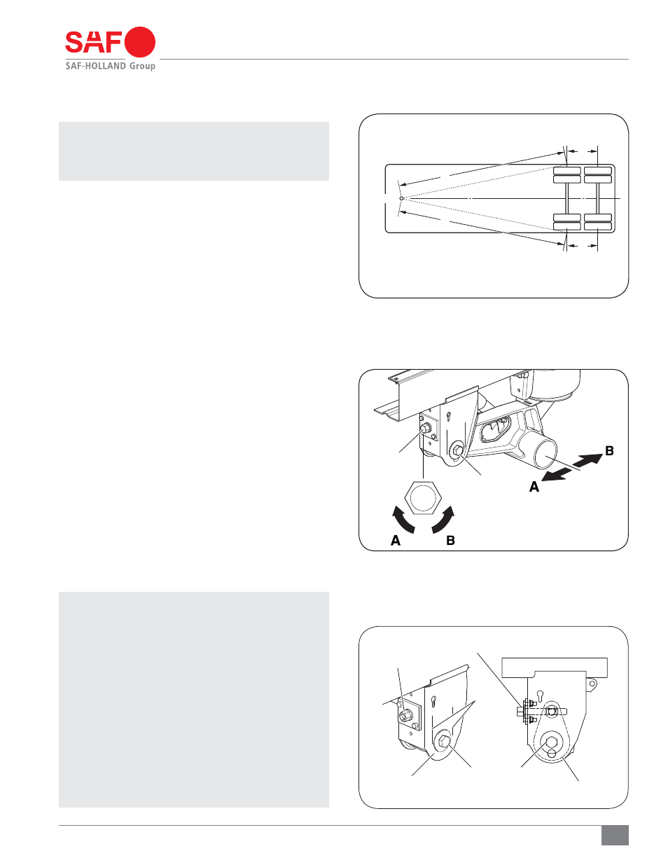
Figure 20
Figure 21
Figure 19
ALIGNMENT
BOLT
WASHER
“A” ARROWS - AXLE FORWARD
“B” ARROWS - AXLE REARWARD
NOTE: 1/2 TURN OF FREE PLAY
IS ACCEPTABLE
A
KINGPIN
B
D
C
13. SwingAlign
™
Axle Alignment
IMPORTANT: Axle alignment can only be achieved if the
lockpin holes are the same distance from the
kingpin, left and right. Axle alignment should
ALWAYS be done while the trailer is empty.
13.1 Alignment Preparation
1. Pull the trailer in a straight line for a sufficient distance
to ensure there are no binds in the suspension.
2. Lock the trailer brakes and pull the trailer straight forward
so the locking pins rest against the rear of the holes in
the body rails.
3. Disengage the trailer parking brakes and ensure the
trailer is empty.
4. Manually measure or use an optical device specifically
designed for alignment measuring to determine the following:
a. Measure the distance from the king pin to
the centerline of the front axle spindles. It is
recommended that spindle extensions be utilized.
b. Dimensions A and B (Figure 19) must be equal to
within 1/8" (3 mm).
c. Measure the distance from the centerline of the front
axle spindles to the centerline of the rear axle spindles.
d. Dimensions C, D, E and F (Figure 19) must be equal
to within 1/16" (1 mm).
13.2 Alignment Instructions
1. Using the measurements from Step 4, align each axle.
Align by rotating the alignment bolt head using a 1-3/8"
socket wrench on the front face of the roadside frame
bracket. Rotate clockwise to move axle forward
(A Arrows); counterclockwise to move axle rearward
(B Arrows) (Figure 20). Approximately 250 ft.-lbs.
/tNXJMMCFSFRVJSFE
IMPORTANT: DO NOT loosen the pivot bolt.
IMPORTANT: Two scribe lines on the side of the frame
bracket indicate maximum adjustment for axle
alignment. If the edge of the visible washer
touches either scribe line the SwingAlign
™
axle alignment adjustment is “out of stroke”
(Figure 15). Inspect and repair trailer
components as necessary and realign.
IMPORTANT: The
SwingAlign
™
design maintains proper
alignment without welding and without
loosening of the pivot connection. DO NOT
weld alignment bolt or pivot bolts.
(Figure 16). If connection requires tightening,
use a 1-11/16" socket wrench and torque to
GUMCT /tN
ALIGNMENT BOLT ASSEMBLY
WASHER
ALIGNMENT
PLATES
SCRIBE
LINES
PIVOT BOLT
ALIGNMENT BOLT
A = B ± 1/8" (3 MM)
C = D ± 1/16" (1.6 MM)