Installation instructions, Stationary fifth wheel installation, Angle mount (see figure 1a and 1b) – SAF-HOLLAND XL-FW492 FW83 and XA-231 FleetMaster LowLube Series Fifth Wheel User Manual
Page 4
4
XL-FW492 Rev D
INSTALLATION INSTRUCTIONS
continued
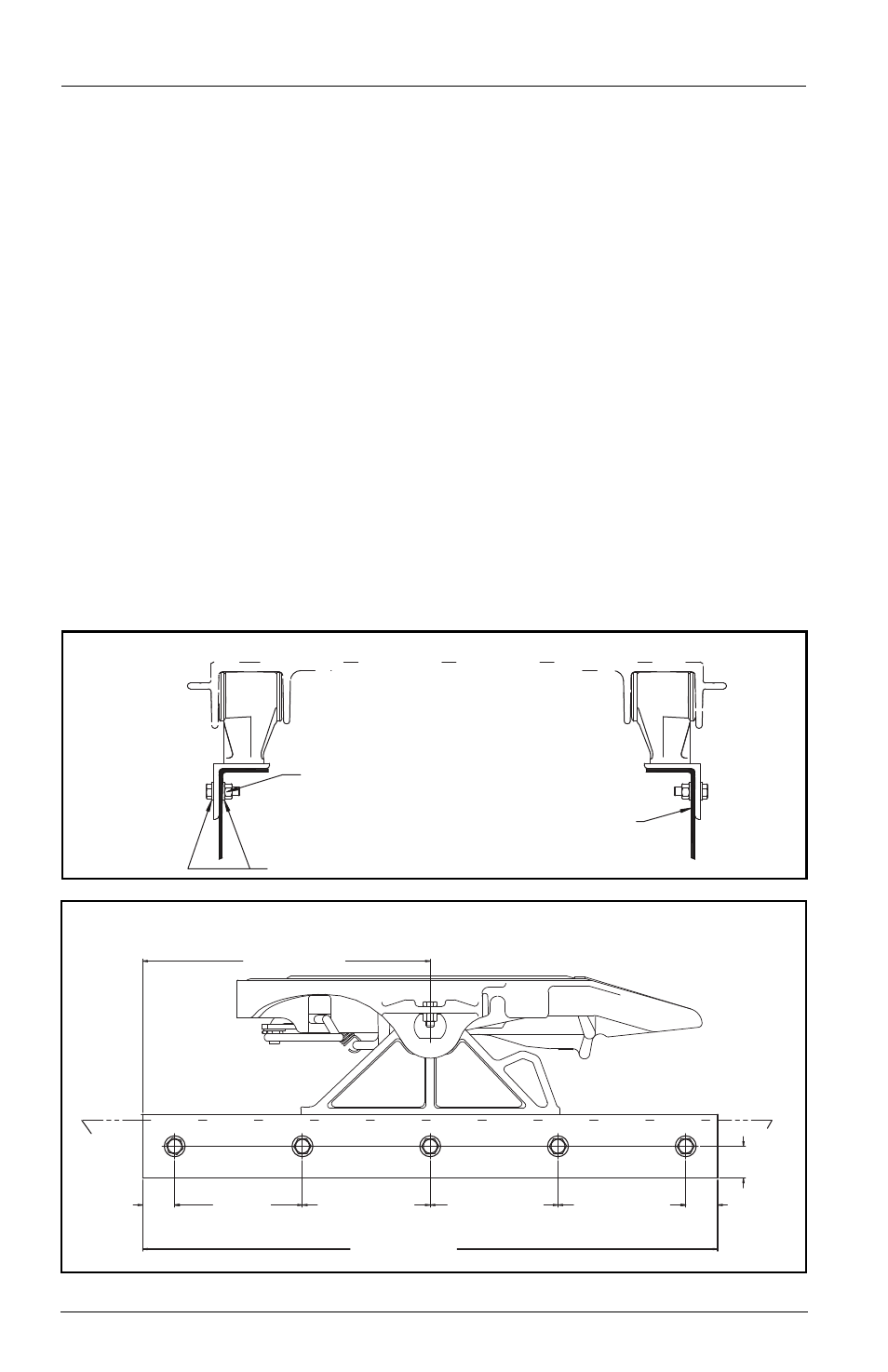
NOTE: The full length of the fifth wheel mounting angle should seat flush on the tractor
frame to prevent flexing of mounting angle and to give uniform weight distribution along
the frame rail.
Stationary Fifth Wheel Installation
Prior to proceeding with the installation of the stationary fifth wheel assembly, carefully
review the “General Safety Information” section on page 2.
Angle Mount
(see Figure 1A and 1B):
Holland standard Angle Mount fifth wheels are provided with the mounting bracket
welded in the center of a standard 4˝ x 4˝ x 36˝ long angle for a specific frame width
dimension. Various heights, frame widths, and angle sizes are available.
In addition to the information given in “Installation: General Recommendations” on page
3, the following sequence should be followed when installing your
angle mount fifth wheel:
1.
Verify the distance between the mounting angles and tractor frame width to insure
a proper fit when the fifth wheel is installed on the tractor.
2.
Reference FIGURE 1B for proper mounting hole location requirements.
3.
Securely position the mounting angle to the tractor frame.
4.
Bolt the angles to the tractor frame following the recommendations in FIGURE 1A.
1A - Keatley July 31
FIGURE 1A (End View)
HARDENED STEEL WASHERS
Lock nuts (5/8˝ dia. Grade C)
5/8˝ dia. Grade 8 bolts minimum
size, tightening torque to bolt
manufacturer charts
TRACTOR
FRAME RAIL
1B - XL-FW492 6-07
FIGURE 1B (Side View)
2.00˝
50.80
MM
18.00˝ MIN
457.20 MM
8.00˝ MAX
203.20 MM
36.00˝ MIN
914.40 MM
2.00˝
50.80
MM
1.00˝ MIN
25.40 MM
8.00˝ MAX
203.20 MM
8.00˝ MAX
203.20 MM
8.00˝ MAX
203.20 MM