Displays, And-tft-7lp-kit tft lcd color module – Purdy AND-TFT-7LP-KIT User Manual
Page 4
Displays
Purdy Electronics Corporation • 720 Palomar Avenue • Sunnyvale, CA 94085
Tel: 408-523-8200 • Fax: 408-733-1287 • [email protected] •
www.purdyelectronics.com
05/09/11
4
AND-TFT-7LP-KIT
TFT LCD Color Module
Pin Description - J501A: LVDS I/O Terminals (Pitch 1.25 mm, 20 Pin, Side Entry Type)
Pin No.
Symbol
I/O
Description
1
VCC
I
Power Supply (3.3 V)
2
VCC
I
Power Supply (3.3V)
3
GND
P
Ground
4
GND
P
Ground
5
RX0-
I
Differential Data Input, CH0 (Negative)
6
RX0+
I
Differential Data Input, CH0 (Positive)
7
GND
P
Ground
8
RX1-
I
Differential Data Input, CH1 (Negative)
9
RX1+
I
Differential Data Input, CH1 (Positive)
10
GND
P
Ground
11
RX2-
I
Differential Data Input, CH2 (Negative)
12
RX2+
I
Differential Data Input, CH2 (Positive)
13
GND
P
Ground
14
CLK-
I
Differential Clock Input (Negative)
15
CLK+
I
Differential Clock Input (Positive)
16
GND
P
Ground
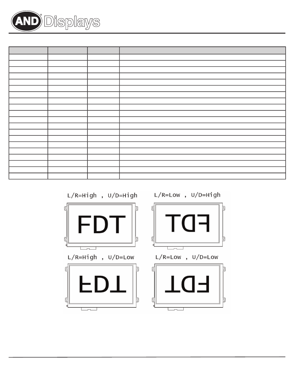
17
L/R
I
Horizontall Display Mode Select Signal
18
U/D
I
Vertical Display Mode Select Signal
19
GND
P
Ground
20
GND
P
Ground