Displays – Purdy ANDpSio8C351-HB-KIT User Manual
Page 3
Purdy Electronics Corporation • 720 Palomar Avenue • Sunnyvale, CA 94085
11/8/06
Tel: 408.523.8200 • Fax: 408.733.1287 • [email protected]
3
www.purdyelectronics.com
Displays
Displays
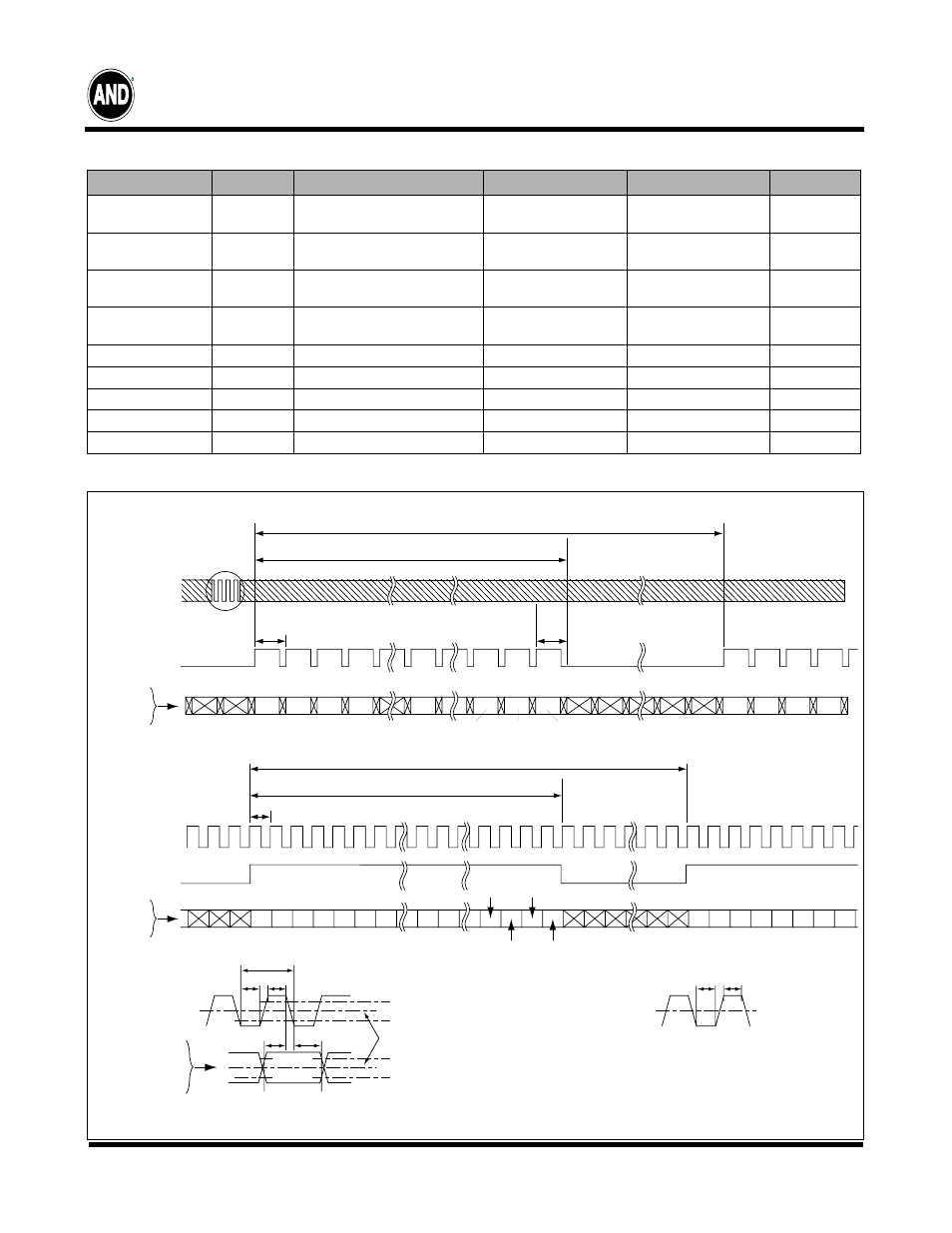
Timing Chart
Timing Specifications
Item
Symbol
Min
Typ
Max
Unit
Frame
Period
t1
604 x t3
–
625 x t3
17.78
628 x t3
17.86
–
ms
Vertical
Display Term
t2
600 x t3
600 x t3
600 x t3
t2 = N •t3
One Line Scanning
Time
t3
944 x t5
(26.3)
1056 x t5
26.4
1064 x t5
–
µs
Horizontal Display
Period
t4
800 x t5
800 x t5
800 x t5
–
Clock Period
t5
24.7
25.0
27.8
ns
Clock “L” Time
t6
9.0
–
–
ns
Clock “H” Time
t7
9.0
–
–
ns
Set Up Time
t8
4.0
–
–
ns
Hold Time
t9
5.0
–
–
ns
t 3
X,2
X,1
X,3
X,4
X,Y
X,598
X,599
X,600
t 2
t 1
t 3
1,Y 2,Y 3,Y 4,Y 5,Y 6,Y 7,Y
X,Y
797,Y
t 4
t 5
t 3
NCLK
ENAB
R5 ~ R0
G5 ~ G0
B5 ~ B0
799,Y
798,Y
800,Y
Vertical Timing
Horizontal Timing
NCLK
ENAB
R5 ~ R0
G5 ~ G0
B5 ~ B0
NCLK
ENAB
R5 ~ R0
G5 ~ G0
B5 ~ B0
t 6
t 5
t 7
NCLK
0.5V
DD
a
b
V
IH
(min) : 0.8 (V)
V
IL
(max) : 0.2 (V)
t 8
t 9
V
IH
(min) : 0.8 (V)
Input Signal Center Level : 0.5 V
DD
V
IL
(max) : 0.2 (V)
Duty (a,b) : 50±10%
VALID
DATA
ANDpSi08C351-HB-KIT