Thermo Pride Premiere XT 16 SEER User Manual
Page 5
5
11. Release the refrigerant charge into the system. Open both the liquid
and vapor valves by removing the plunger cap and with an allen
wrench back out counter-clockwise until valve stem just touches the
chamfered retaining wall. See PRECAUTIONS DURING BRAZING
SERVICE VALVE.
12. Replace plunger cap finger tight, then tighten an additional 1/12 turn
(1/2 hex flat). Cap must be replaced to prevent leaks.
See "System Charge” section for checking and recording system
charge.
SECTION IV: ORIFICE INSTALLATION
Install Schrader Valve Core and Orifice as follows:
1. Relieve the holding charge from the indoor coil by depressing the
Schrader valve stem located in the end of the suction line. Cut the
spundown copper to allow installation of the suction line.
2. Slide indoor coil out of cabinet far enough to gain access to equal-
izer fitting on the suction line.
3. After holding charge is completely discharged remove black plastic
cap on equalizer fitting.
4. Install Schrader Valve Core supplied with the outdoor unit into
equalizer fitting using a valve core tool.
5. Loosen and remove the liquid line fitting from the orifice distributor
assembly. Note that the fitting has right hand threads.
6. Install proper size orifice supplied with outdoor unit. Refer to sup-
plied Tabular Data Sheet for specific orifice size and indoor coil
match up.
7. After orifice is installed reinstall the liquid line to the top of the orifice
distributor assembly. Hand tighten and turn an additional 1/8 turn to
seal. Do not over tighten fittings.
8. Leak test system.
9. Replace black plastic cap on equalizer fitting.
10. Slide indoor coil back into cabinet.
SECTION V: TXV INSTALLATIONS
For installations requiring a TXV, the following are the basic steps for
installation. For detailed instructions, refer to the Installation Instructions
accompanying the TXV kit.
Install TXV kit as follows:
1. Relieve the holding charge from the indoor coil by depressing the
Schrader valve stem located in the end of the suction line. Cut the
spundown copper to allow installation of the suction line.
2. After holding charge is completely discharged, loosen and remove
the schraeder cap seal.
3. Loosen and remove distributor cap seal.
4. Install the thermal expansion valve to the orifice distributor assembly
with supplied fittings. Hand tighten and turn an additional 1/4 turn to
seal. Do not overtighten fittings.
5. Install the liquid line to the top of the thermal expansion valve with
fitting supplied with the liquid line. Hand modify the liquid line to
align with casing opening. Hand tighten the liquid line and an addi-
tional 1/4 turn to seal.
6. Install the TXV equalizer line into the vapor line as follows:
a. Hand tighten the 1/4” SAE nut to the schraeder fitting and an
additional 1/3 turn to seal.
7. Install the TXV bulb to the vapor line near the equalizer line, using
the bulb clamp(s) furnished with the TXV assembly. Ensure the bulb
is making maximum contact.
a. Bulb should be installed on a horizontal run of the vapor line if
possible. The bulb should be installed on top of the line.
b. If bulb installation is made on a vertical run, the bulb should be
located at least 16 inches from any bend, and on the tubing
sides opposite the plane of the bend. The bulb should be posi-
tioned with the bulb tail at the top, so that the bulb acts as a res-
ervoir.
c. Bulb should be insulated using thermal insulation provided to
protect it from the effect of the surrounding ambient tempera-
ture. Cover completely to insulate from air-stream.
All connections to be brazed are copper-to-copper and should be
brazed with a phosphorous-copper alloy material such as Silfos-5 or
equivalent. DO NOT use soft solder.
Install the TXV bulb to the vapor line near the equalizer line, using the
two bulb clamps furnished with the TXV assembly. Ensure the bulb is
making maximum contact. Refer to TXV installation instruction for view
of bulb location.
Never attempt to repair any brazed connections while the system is
under pressure. Personal injury could result.
Failure to install Schrader Valve Core on orifice applications could
result in total refrigerant loss of the system!
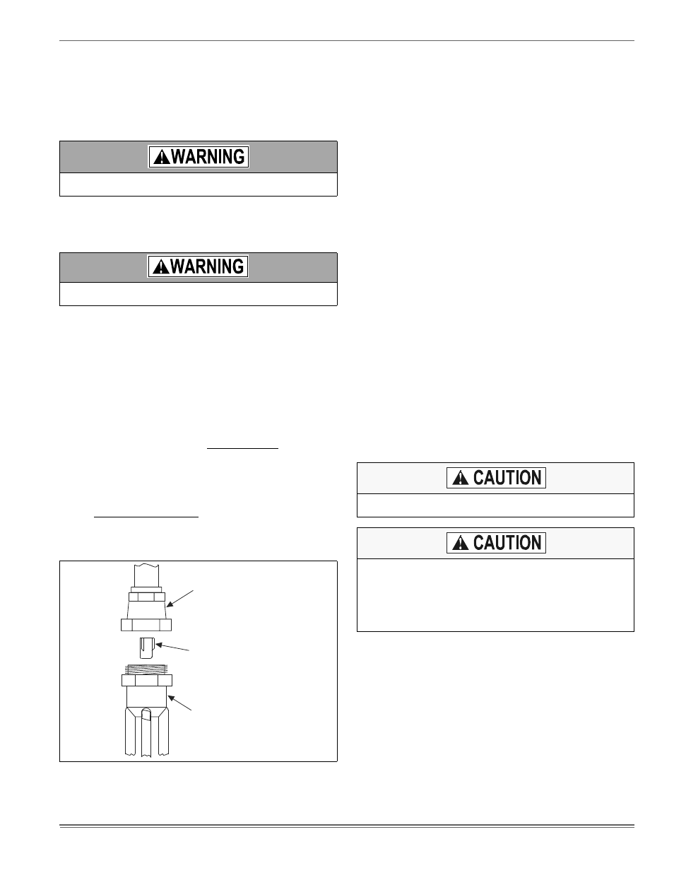
FIGURE 5: Orifice Installation
LIQUID LINE
SWIVEL COUPLING
(This fitting is a right-hand thread,
turn counter-clockwise to remove)
ORIFICE
DISTRIBUTOR
In all cases, mount the TXV bulb after vapor line is brazed and has
had sufficient time to cool.
Dry nitrogen should always be supplied through the tubing while it is
being brazed, because the temperature required is high enough to
cause oxidation of the copper unless an inert atmosphere is provided.
The flow of dry nitrogen should continue until the joint has cooled.
Always use a pressure regulator and safety valve to insure that only
low pressure dry nitrogen is introduced into the tubing. Only a small
flow is necessary to displace air and prevent oxidation.