Connection diagram, Use of e.o.a. contact, Wiring – SAF OPAL LT User Manual
Page 6: R vs -ax
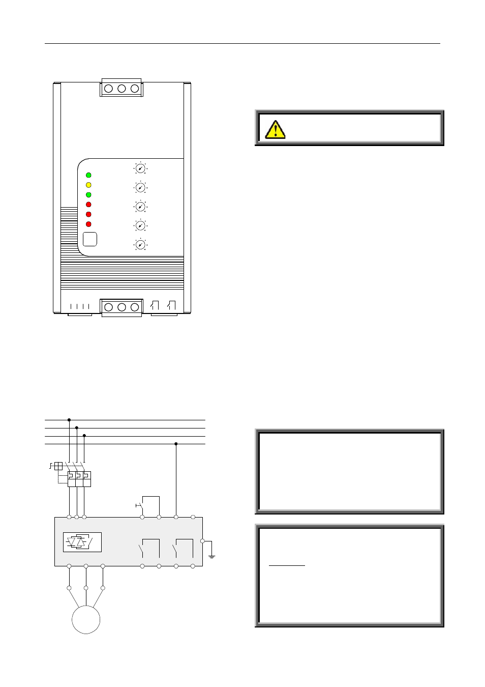
Wiring
5
Block and Connection Diagram
NOTE: The RVS-AX incorporates an internal control
voltage transformer connected to phases L1&L3, in
case of phase loss of L1 or L3 the starter will stop the
motor. In case of phase loss for L2 the phase loss fault
will trip the starter only if Terminal 3 – Neutral, is
used).
Stop / Start......................................... Terminals 1 - 2
By voltage free contact (Dry contact)
T1/U
T2/V T3/W
End of
A cce l e ra ti o n
Fau lt
Start
Stop
N
1
2
3
4
O n
R am p-Up/D ow n
R un
O verload
Phas e Loss
R eset
O ver Tem p.
Motor FLC
50%
100%
Initial Voltage
10%
50%
C urrent Lim it
100%
400%
R am p-Up
2
30 Sec .
R am p-D ow n
30 Sec .
0.2
1
L
2
L
3
L
R VS -AX
Reduced V oltage S tarter
5
6
7
8
Close: Start command.
Open: Stop command.
Warning
Do not apply voltage to terminals 1 - 2.
Neutral ...................................................... Terminal 3
Neutral wire (when used) is required only for operation
of the Phase Loss Protection (Phase Loss can not be
detected when Neutral is not connected to Terminal 3).
See detailed description in “Phase Loss” explanation.
Open
terminal – not connected ................ Terminal 4
End of Acceleration (E.O.A) .......... Terminals 5 - 6
Voltage free, N.O., 8A / 250VAC, 2000VA max.
The contact closes after the time adjusted on the
"Ramp-Up" potentiometer. The contact returns to its
original position on stop signal, on fault condition,
upon voltage outage and at the beginning of Soft Stop.
Use of E.O.A. Contact
This contact can be used for:
• Activating a valve after a compressor has reached
full speed
• Loading a conveyor after the motor has reached
full speed.
Fault contact .................................... Terminals 7 - 8
Voltage free, N.O., 8A / 250VAC, 2000VA max.
The contact closes upon operation of any fault. The
contact returns to its original position (after the fault
has been removed) upon reset, or upon disconnection
the Mains voltage.
Connection Diagram
M
1
/L
1
RVS -A X
W 1
V 1
U1
T1
/U
T2
/V
T3
/W
L1
L2
L3
Neutral
3
8
R1
A
R1
C
R2
A
R2
C
1
2
S
ta
rt / S
to
p
N
eut
ral
4
No
t Us
e
d
Fault
End Of
Acceleration
Ground
3
/L
2
5
/L
3
7
6
5
I>
I>
I>
Q1
x 3
S1
Warning
Do not use the Fault contact to trip an upstream
contactor. When the Fault contact trips the
upstream contactor, Mains voltage will be
disconnected, thus resetting the starter and the
motor will restart instantaneously upon voltage
restoration (see Fault Resetting).
Warning
Start/Stop with a maintained contact!
When the line contactor is operated by a
maintained contact, in case of Mains failure, the
motor will be automatically restarted upon
voltage restoration.
When resetting after a fault with the Reset
button, the motor will restart upon fault reset.
It is therefore recommended not to connect the
fault relay to the line contactor.